Overview > Finite Element Anaylsis and VisualFEA > Procedure of finite element analysis using VisualFEA
![]()
|
Overview > Finite Element Anaylsis and VisualFEA > Procedure of finite element analysis using VisualFEA |
|
|
|
|
||
Procedure of finite element analysis using VisualFEA
The whole procedure of finite element analysis can be processed consecutively by a single executable module of VisualFEA. However, there is an alternative to split the procedure into a few stages and process each stage separately using different programs, especially employing external solver for main computation of the analysis.
> Stages of finite element analysis
The general procedure of finite element analysis can be split largely into 3 stages: preprocessing for preparation of modeling data, processing for assembly and solution of the equations, and postprocessing for visualization of analysis results.
Some stages and procedures may be added or dropped depending on the analysis subject and the project contents.
> Finite element analysis using VisualFEA
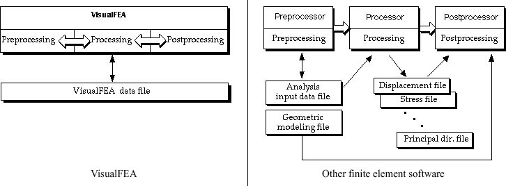
Finite element analysis systems are generally composed of separate programs for each of the above 3 stages, and they are called preprocessor, solver and postprocessor respectively. On the other hand, VisualFEA has all the components integrated in one executable program. Thus, the whole procedure of finite element analysis can be completed by a single execution of VisualFEA. It is not necessary to pass the data from one program to another. There is only one data file for a project. All the modeling and analysis data are stored to and retrieved from the file. Once the file is opened, all data related with the finite element analysis are available for internal processing.
In some cases, the stages are not clearly separated, but intermixed with each other. It is possible to go back and forth freely between two different stages. In frame analysis, for example, the computed results are displayed graphically right after its geometry or attribute data are altered. In such cases, users can hardly distinguish the stages.
The software and data constructions are compared between VisualFEA and other programs. VisualFEA has a monolithic construction for both software and data, while most of other programs have complex constructions with multiple programs and a number of data files. Such a simple construction makes usage of VisualFEA simple and efficient.

< Comparison of software and data construction >
> Mixed use of VisualFEA and external solvers
Although the entire procedure of finite element analysis can be completed by a single execution of VisualFEA as described above, there is an alternative procedure in which an external solver is used together with VisualFEA . VisualFEA has powerful pre- and postprocessing capability, but can handle only relatively limited types of analysis. Therefore, it is sometimes desirable to accomplish pre- and postprocessing using VisualFEA, but adopt an external solver for analysis. In this case, input data for the analysis is created by VisualFEA, and supplied to the external solver, and the results computed by the solver are again retrieved to VisualFEA for graphically visualization. If existing third party software is used, an additional program for data interface between VisualFEA and the solver may be necessary. In case the solver is developed by the user, the computed results may be written directly in the VisualFEA file, so that neither extra files nor interface data files are necessary. The data interface with external solvers is described in detail in Chapter 10.
|
|
|
|