![]()
| Diagrams for Frame Analysis > Diagrams for Truss and Rigid Frame > Visualizing analysis data of 2-D and 3-D rigid frames |
|
|
|
|
||
Visualizing analysis data of 2-D and 3-D rigid frames
If the analysis type is set to 2-D rigid frame, ![]() menu
has the items as shown below. As describe at the beginning of this chapter,
the menu is composed of 3 parts. The first part of the menu has items of axial
force, shear force and bending moment as
for member forces. There are also support reaction and displacement items.
menu
has the items as shown below. As describe at the beginning of this chapter,
the menu is composed of 3 parts. The first part of the menu has items of axial
force, shear force and bending moment as
for member forces. There are also support reaction and displacement items.

If the analysis type is set to 3-D rigid frame, ![]() menu
has more items as shown below. The first part of the menu includes 6 components
of an axial force, 2 shear forces, 2 bending moments, and a torsional
moment. There are also support reaction and displacement items.
menu
has more items as shown below. The first part of the menu includes 6 components
of an axial force, 2 shear forces, 2 bending moments, and a torsional
moment. There are also support reaction and displacement items.

The menu items are enabled only when the model is complete for solution, and thus the corresponding data are available. The diagram is displayed instantly when the menu item is chosen. The displayed diagram is indicated by a check mark in front of the menu item.
The components of member force are given with respect to local coordinates as shown in the figure below. The sign of internal forces are determined in accordance with conventional usage.

< Member forces in 2 and 3-D rigid frames >
> Displaying axial force diagram
To display the axial force (A) diagram for 2-D and 3-D rigid frame, choose
"Axial Force" item from ![]() menu.
Axial force is equivalent to that of trusses. But its value is not necessarily
uniform in a rigid frame member. Therefore, diagram is the only option to represent
the axial force in rigid frames, differently from the case of t russes in which
member force is uniform throughout the whole length and accordingly its magnitude
can be represented by a single text string.
menu.
Axial force is equivalent to that of trusses. But its value is not necessarily
uniform in a rigid frame member. Therefore, diagram is the only option to represent
the axial force in rigid frames, differently from the case of t russes in which
member force is uniform throughout the whole length and accordingly its magnitude
can be represented by a single text string.
> Displaying shear force diagram for 2-D rigid frame
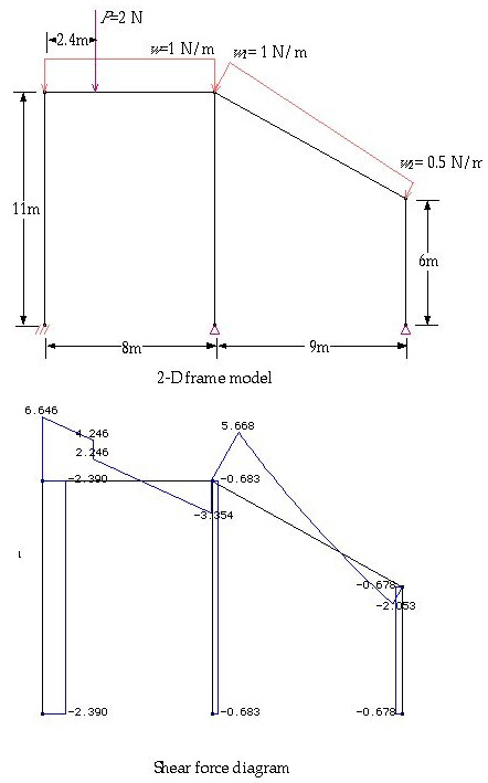
There is only one shear force component(S) for 2-D rigid frame. To display
the shear force diagram, choose "Shear Force" item from ![]() menu.
The diagram reflects the variation of shear forces within a member in its length
direction. The values are shown in text string at member ends, at points of
abrupt change, and at the points of local maximum or minimum.
menu.
The diagram reflects the variation of shear forces within a member in its length
direction. The values are shown in text string at member ends, at points of
abrupt change, and at the points of local maximum or minimum.
> Displaying bending moment diagram for 2-D rigid frame
There is only one bending moment component (M) for 2-D rigid frame. To display the bending moment diagram choose "Bending Moment" command from the menu. The diagram reflects the variation of bending moments within a member in its length direction. The values are shown in text string at member ends, at points of abrupt change, and at the points of local maximum or minimum.

< Shear force diagram for a 2-D rigid frame >
< Bending moment diagram >
> Displaying deformed shape of rigid frame
In order to display the deformed shape of 2-D or 3-D rigid frame, choose "Displacement" command from the menu. The deformed shape of a rigid frame member is no longer straight, because frame members are subject to not only axial but also bending deformation.

< Deformed shape >
> Displaying support reactions of rigid frame
In order to display the support reactions of 2-D or 3-D rigid frame, choose "Reaction" command from the menu. The reactions are represented by a force symbol and the text of its magnitude. The reactions are shown only for constrained DOFs with non-zero value at supported nodes.

< Deformed shape >
> Displaying shear force diagram for 3-D rigid frame
There are two shear force components (Sy and Sz) for 3-D frames. To display the shear force diagram, choose "Shear Force y" or "Shear Force z" item from menu. Here, y and z directions are given in local coordinates defined on the basis of member axis.
An example of 3-D frame modeling and shear force diagram is shown below. In this example, frame members are rendered in shading. Representation of frame members by shading is not essential, but desirable for 3-D frames to improve the understandability of the diagram. In order to get such an image, set the render mode to shading by choosing "Shading" from menu.

< Shear force diagram for a 3-D rigid frame >
> Displaying bending or torsional moment diagram for 3-D frame
There are two bending moment components(My and Mz) and a torsional moment(T)
for 3-D frames. To display the diagrams of bending moment about y and z axis,
choose "Bending Moment y" and "Bending Moment z" items respectively
fro m menu. To display the torsional moment diagram, choose "Torsional
Moment" from the ![]() menu.
menu.

< Bending moment z (Mz) diagram for a 3-D rigid frame >
|
|
|
|