Examining Element Stiffness Matrix
|
Examining Element Stiffness Matrix |
|
|
| |
||
Displaying element stiffness information of frames
Truss and rigid frame are collectively designated as frame in this manual. The stiffness equations of frame members are given by
![]()
where Ke the element stiffness matrix,
Fe is the force vector, and is the
displacement vector in global coordinates. The element stiffness information
is composed of the stiffness matrix itself and other items related to its computation.
Root level items
The element stiffness information for frame members has the following root level items:
This item is to display the modeling data related to the geometry of the member,and has the following child items.
| Nodal coordinates: Cartesian coordinates of the nodes at both ends of the member. | |
| - Node 1 : The coordinates of a node of the member (x1,y 1,z1). | |
| - Node 2 : The coordinates of the other node of the member (x2,y2,z2). | |
| Section and length: Section properties, length and direction of the member. | |
| - Area : Section area, A | |
|
- Iz : 2nd moment of area about z axis, Iz(for rigid frame only) |
|
| - Iy : 2nd moment of area about y axis, Iy(for 3-D rigid frame only) | |
| - Ix : Polar moment of area, J (for 3-D rigid frame only) | |
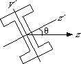
| - Section angle: angle between the principal axis of the section and the axis determined by the member direction, q (for 3-D rigid frame only) . | |
 |
|
|
- Length: The length of the member, L. The length is computed from the nodal coordinates. |
|
|
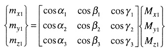
- Dir. cos : Direction cosines. For 2-D frames, the direction cosines [ cos a sin a ] are determined by the angle, a between the axial direction of the member the the global X axis. For 3-D frames, 3 angles of axial direction a1, b1, and g1 are defined with respect to the global X, Y and Z axis respectively. And, the direction cosines are [cos a cos b cos g]. |
|
| The angles are computed from the nodal coordinates. Two other orthogonal directions in local coordinates can be derived from the direction cosines. |
The rotation matrix and the transformation matrix consist of the direction
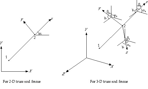
<Angles between Local and global coordinate axis>
Property
Material property of the member has only 2 constants: elastic modulus, and Poisson? ratio. The shear modulus is computed from these 2 constants.
|
“Elastic modulus" : Young’s modulus of elasticity, E. |
|
| “Poisson’s ratio" : Poisson’s ratio, n (for 3-D rigid frame only). |
Stiffness matrix in local coordinates
The element stiffness matrix in local coordinates relates the nodal forces and the nodal displacements of a member in local coordinates. That is,
![]()
where fe, ke and de are respectively the element force vector, element stiffness matrix, and element displacement vector, all in local coordinates.
The entries of stiffness matrix in local coordinates are obtained directly from explicit equations without going through integration procedure. Each entry is given as a function of element length, section area, area moment of inertia, modus of elasticity, and so on.
This equation can be displayed in place of the numerical values of the stiffness entries. The numerical expression and the symbolic expression of the equations are toggled by clicking the desired entry.
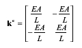
For 2-D and 3-D trusses, only axial d.o.f. are effective, and thus stiffness relations in local coordinates have 2 d.o.f., one at each end of the member. The matrix relates the force vector [ f1 f2 ]and the displacement vector [ d1 d2 ]in local coordinates.
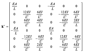
For 2-D rigid frames, there are 3 d.o.f. at a node and thus 6 d.o.f. for a member.
The following 6 X 6 stiffness matrix gives the relation between the force vector [ fx1 , fy1 , m1 , fx2 , fy2 , m2 ]and the displacement vector [ u1, v1, q1, u2, v2, q2 ]in local coordinates.
For 3-D rigid frames, there are 6 d.o.f. at a node and thus 12 d.o.f. for a member.
The stiffness relations are expressed by the 12 X 12 matrix. The stiffness matrix gives the relation between the force vector and the displacement vector in local coordinates.
Rotation matrix
The rotation matrix is a matrix transforming the nodal force or displacement vector from global coordinatesto local coordinates. The transformations at node i are expressed as

where R is the rotation matrix, fi and di are force and displacement vectors in local coordinates, and Fi and Di are force and displacement vectors in global coordinates. For example, the nodal force vector at node 1 can be transformed from the global coordinates into the local coordinates by
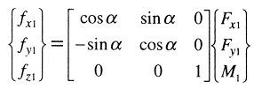
in the case of 2-D rigid frame. Thus the rotation matrix is
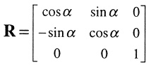
The rotation matrices for 2-D and 3-D truss elements are respectively
![]()
and
![]()
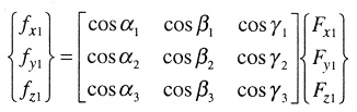
The rotation matrix for a 3-D rigid frame is
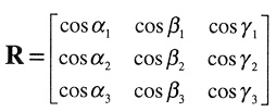
where the angles a2 , b2 , g2 , a3 , b3 and g3 are computed from a1 , b1 , g1. For 3-D rigid frame, translational d.o.f. and rotational d.o.f. are separately transformed.
That is,
and,
Stiffness matrix in global coordinates
The stiffness matrix ke in local coordinates is transformed into global coordinates,using coordinate transformation matrix, T.
K e = T T K e T
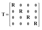
The transformation matrix is composed of rotation matrix, R. For 2-D truss, 3-D truss and 2-D rigid frame, the transformation matrix is given by

For 3-D rigid frame, the transformation matrix is
The element stiffness matrix in global coordinates is obtained by coordinat etransformation of the stiffness matrix in local coordinates, as already described earlier. The stiffness matrix can be represented by an n x n matrix.
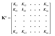
where n is the number of d.o.f. for an element, and is 4, 6, 6, and 12 respectively for 2-D truss, 3-D truss, 2-D rigid frame and 3-D rigid frame.
Equivalent nodal forces
In VisualFEA/CBT, equivalent nodal forces are defined only for 2-D and 3-D rigid frames.
The information of the equivalent nodal forces is expanded in 2 items, one in local coordinates and the other in global coordinates.
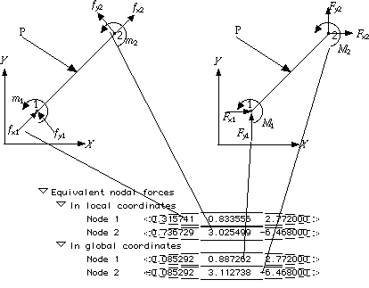
< Information of equivalent nodal forces >
|
|
|
|