Examining Element Stiffness Matrix
|
Examining Element Stiffness Matrix |
|
|
| |
||
Displaying element stiffness information of continuum structures
The stiffness equations of continuum structures can be expressed by the same equations for frames explained in the previous section. However, the procedure of computing the element stiffness matrix of a continuum structure is totally different from that of a frame. Thus, contents of element stiffness information for continuum stru c t u res are diff e rent from those for frames. The stiffness matrix is obtained generally by the following integration:
![]()
Where B is the strain-displacement matrix, and E is the constitutive matrix. In actual computation, the integration is evaluated numerically. Numerical integration can be expressed by the following summation equation.
![]()
for plane strain and 3-D solid cases, and
![]()
for plane stress, axisymmetric, plate bending and shell analysis, where i is the index for each integration point and m is the number of integration points. Bi, Ei,ti , Ji and wi a re respectively strain-displacement matrix, constitutive matrix, thickness, Jacobian determinant and weight of integration at integration point i. They are included in the element stiffness information.
Root level items
The element stiffness information for continuum structure has the following root level items:
Geometry
Geometry includes the information on the position of each node, and thickness of the element if applicable.
Propert
The element property is defined by 2 elastic constants: modulus of elasticity and Poisson's ratio. The constitutive matrix is determined from these constants.
| ”Elastic modulus” : Young’s modulus of elasticity applied to all the integration points within the element . | |
| “Poisson’s ratio” : Poisson’s ratio applied to all the integration points within the element . | |
| “Stress-strain matrix” : Constitutive matrix determined by the elastic modulus and Poisson’s ratio. |
Integration scheme
There is a sub-item for each integration point. A sub-item has the following information:
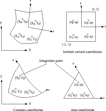
< Position of integration points in Cartesian and natural coordinates>
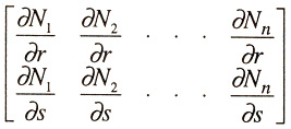
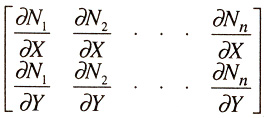
Shape function and Jacobian matrix
Shape function and Jacobian matrix form a sub-item for each integration point. A sub-item has the following information:
| “Jacobian inverse” : Inverse matrix of Jacobian matrix, J-1. | |
|
“Jacobian determinant” : Determinant of Jacobian matrix, J =|J|. |
Strain-displacement matrix
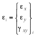
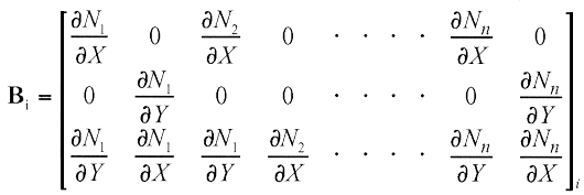
This is the matrix relating the strain at each integration point to the nodal displacements. The relation between strain and nodal displacements at integration point i is expressed by the equation,
![]()
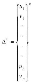
where e, Bi and De are strain vector at integration point i, strain-displacement matrix and nodal displacement vector. In the case of plane stress, for example,
 |
|
 |
and
 |
This item displays the portion of the numerical integration of the element stiffness matrix at integration point i. The matrix is evaluated at integration point i by the following equation.
![]()
for plane strain and 3-D solid cases, and for plane stress, axisymmetric, plate bending and shell analysis.
![]()
This item displays the element stiffness matrix obtained by numerical integration.
The element stiffness matrix can be expressed in generic form as follows:
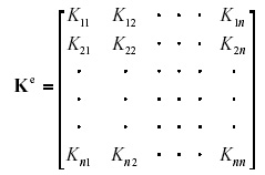
where n is the number of d.o.f. within the element.
|
|
|
|