![]()
![]()
![]()
![]()
| Basic User Interface > Grid and 3-D Cursor > Grid |
|
|
|
|
||
Grid
| Grid planes are used for convenience of inputting coordinates. Only one grid plane (xy plane) is used for 2-dimensional modeling, but three planes (xy, yz, and zx planes) are used for 3-dimensional modeling. Each of the grid planes can be independently moved forward and backward, resized, or turned on and off. |
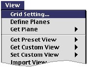
> Setting grid
The properties and the appearance of the grid planes are set by using the "Grid Setting" dialog. The dialog has the following items:
 |
Scale : the actual distance between two adjacent grid lines | |
| Pitch : the number of screen pixels between two adjacent grid lines, which is assumed to be counted in the view state without any transformation. | ||
| Subdivisions : the number of subdivisions between two adjacent grid lines. A grid cell is temporarily divided into subcells depending on this value. | ||
| Show coordinate axis : Check this box to display the coordinate axis letters 'X', 'Y' and 'Z'. | ||
|
|
This grid setting can also be done by using pre f e rence dialog.
In this case, the setting is applied as the default setting for future sessions.
The number of subdivisions can also be set simply by using F keys, which is
explained in "Subdividing grid."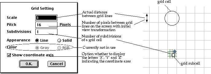
< Grid setting >
> Turning grid planes on and off
All the grid planes are initially on, and the state of the grid planes are
indicated by the shape of the tool buttons ![]() ,
,![]() and
and![]() respectively for the xy, yz and zx planes. Clicking these buttons toggle each
of the planes on and off. The buttons are shaped respectively
respectively for the xy, yz and zx planes. Clicking these buttons toggle each
of the planes on and off. The buttons are shaped respectively ![]() ,
,![]() and
and ![]() in off state. Turning off a grid plane not only hides the plane, but also suppresses
its function in future operations.
in off state. Turning off a grid plane not only hides the plane, but also suppresses
its function in future operations.
> Moving grid planes
Each of the three grid planes (xy, yz, and zx planes) can be moved independently by using either the mouse or the keyboard. The grid planes can be moved by using the mouse by the following steps:
| 1) Start the grid movement tool by pressing the tool button
|
|
|
2) Do the view transformation if necessary. It is easy to move a plane facing obliquely to the front of the screen. |
|
| 3) Place the screen cursor over the grid plane to move. The
cursor shape changes into |
|
|
4) Press the mouse button. The cursor shape changes into |
|
| 5) Drag the cursor in the direction to move the grid plane. The grid plane moves along with the cursor movement. | |
| 6) Release the mouse button. The cursor shape returns to |
|
|
7) Repeat 3) - 6) for each of the grid planes until all the grid planes are in the desired position. While the grid planes are moving, the coordinates of the changing grid origin are displayed in the text box at the bottom of the tool palette. |
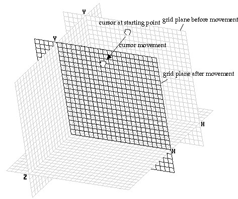
< Moving grid planes by mouse >
On the other hands, the coordinates of the grid origin can be entered directly using the text box. Each of the grid planes is moved so that new grid origin is formed at the position of the entered coordinates.
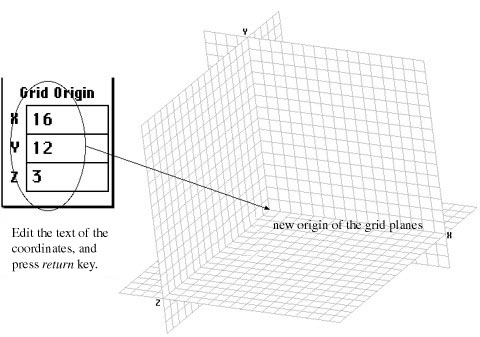
< Moving grid planes by keyboard >
> Resizing grid planes
|
Each of the three grid planes can be expanded or shrunken to the appropriate size by the following steps: |
||
| 1) Start the grid resizing tool by pressing the tool button
|
||
| 2) Place the screen cursor over an edge of the grid plane
to resize. The cursor shape changes into |
||
|
3) Press the mouse button. The cursor shape changes into |
||
| 4) Drag the cursor in the direction to expand or shrink the grid plane. The grid plane expands or shrinks along with the cursor movement. | ||
| 5) Release the mouse button. The cursor shape returns to |
||
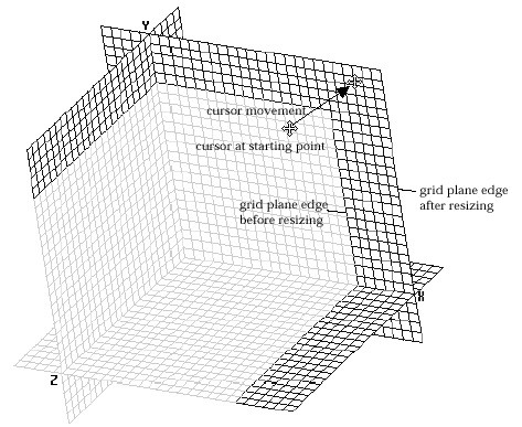
< Resizing grid planes >
> Subdividing grid
A grid can be subdivided as shown below. In order to get the subdivided grid,
press F keys(F1 - F24). The F number corresponds to the number of divisions.
For example, ![]() will
set the division into 3,
will
set the division into 3, ![]() into
12, and
into
12, and ![]() into
1(no subdivision).
into
1(no subdivision).
It is convenient to use subdivided grid points in entering a coordinates of a point which does not fall on a grid point, but on a subdivided point. This action is only e ffective under input or modification mode. Coordinate input using subdivided grid is achieved by the following steps:
|
1) Move the screen cursor near the point of input. |
|
| 2) Press the mouse button. The grid cell containing the screen
cursor is subdivided at the moment the mouse button is pressed, and one
of the subdivided grid points is marked by |
|
| 3) Drag the |
|
| 4) Release the mouse button. The coordinates of the point
with |
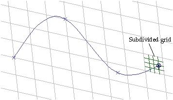
<Entering points using subdivided grid>
|
|
|
|