![]()
![]()
![]()
![]()
| Basic User Interface > Inputting Coordinates of Points > Inputting coordinates using mouse |
|
|
|
|
||
Inputting coordinates using mouse
The coordinates of a control point may be entered simply by a mouse click. The position of the screen cursor at the moment of clicking is related with a point in 3- dimensional space, which is one of the following five kinds of points:
| a point constrained on grid plane | |
| a grid point | |
| a control point of an existing curve or a surface primitive | |
| an existing node point | |
| 3-dimensional cursor point |
Thus, the 3-dimensional coordinates of the point are entered for a new contro l point.
> Entering coordinates using grid planes
The coordinates of a point can be entered using a grid plane (xy, yz or zx plane) by the following steps:
 |
1) Turn on the grid plane, if it is off. |
|
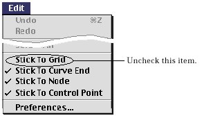
2) Uncheck "Stick to Grid" item of |
|
|
3) Move the cursor over the grid plane image. |
|
|
The screen cursor changes into shape. |
|
|
4) Press the mouse button. |
|
|
While the mouse is pressed, the coordinates at the cursor point are echoed in the text boxes at the bottom of the tool palette. If you move the mouse keeping the mouse button pressed, the text of the coordinates constantly changes in accordance with the cursor position. |
|
|
5) Release the mouse button. |
|
|
The coordinates of the point are entered by the coordinates echoed in the text box at the moment the mouse button is released. |
The coordinates entered as above is constrained by the grid plane. If the screen cursor is contained within the image of any grid plane, xy, yz, or zx, the position of the cursor is mapped into 3-dimensional space by the plane. Accordingly, the cursor point is related to a point on the plane. In other words, while the cursor moves on the screen, the movement of the corresponding point in 3-dimensional space is constrained over the surface of the plane.
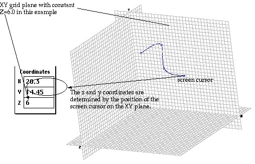
< Example of entering coordinates using the grid planes >
> Entering coordinates using grid points
A grid point is a point at which two orthogonal grid lines cross on a grid plane. T h ree-dimensional coordinates can be entered using these grid points by the following steps.
 |
1) Turn on the proper grid plane, if it is off. |
|
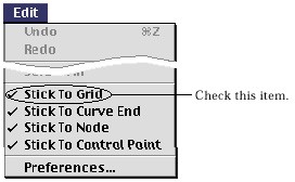
2) Check "Stick to Grid" item of menu, if it is unchecked. |
|
|
3) Move the cursor close to a grid point. |
|
|
4) Press the mouse button. |
|
|
At the moment the mouse button is pressed, the grid point closest to
the s c reen cursor is marked by |
|
|
5) Release the mouse button. |
|
|
The coordinates of the point are entered by the coordinates of the grid point echoed in the text box at the moment the mouse button is released. |
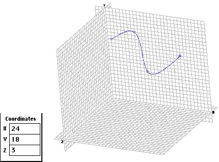
< Example of entering coordinates using grid points >
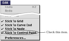
> Entering coordinates using control points
The coordinates can be entered using control points of previously created curves or surface primitives by the following steps.
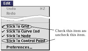
The coordinates can be entered using only the end points, instead of contro l points, of previously created curves or surface primitives. For example, the end points of a spline curve, but not the control points in the middle are used for entering coordinates. To use this option, "Stick to Control Point" item should not be checked, while "Stick to Curve End" item is checked.
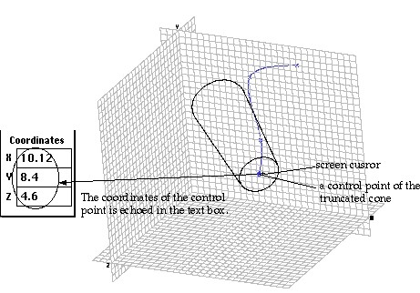
< Example of entering coordinates using a control point of a primitive surface >
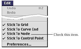
> Entering coordinates using nodes
The coordinates can be entered using nodes by the following steps.
 |
|
|
2) Move the cursor close to a node. |
|
| 3) Press the mouse button. | |
| At the moment the mouse button is pressed, the node closest
to the scre e n cursor is marked by |
|
| 4) Release the mouse button. | |
|
The coordinates of the point are entered by the coordinates of the node echoed in the text box at the moment the mouse button is released. |
|
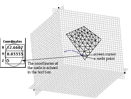
< Example of entering coordinates using a node >
> Entering coordinates using 3-D cursor
VisualFEA has a special inputting aid called 3-D cursor. The 3-D cursor is useful in defining a position in 3-dimensional space in conjunction with grid or other points like nodes or control points. The coordinates can be entered using this 3-D cursor by the following steps.
 |
1) Turn on the 3-D cursor. |
| Clicking the 3-D cursor button |
|
|
2) Move the 3-D cursor point to the desired position. |
|
| The method of moving the 3-D cursor is explained in" 3-D Cursor" section of this chapter. | |
|
3) Move the screen cursor over the 3-D cursor point. |
|
| 4) Click the mouse button. | |
| Then, the 3-D cursor point is marked by , and the coordinates of the 3-D cursor point are echoed in the text boxes at the bottom of the tool palette. |
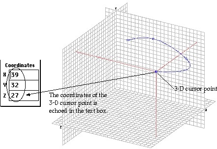
< Example of entering coordinates using 3-D cursor >
|
|
|
|