![]()
![]()
![]()
![]()
| Curves and Surface Primitives > Handling Curves and Surface Primitives > Processing curves and surface primitives |
|
|
|
|
||
Processing curves and surface primitives
> Linking curves
Linking is connecting more than two curves serially and forming a linked curve. A linked curve is treated as a single curve in various actions such as selecting, deleting, cutting, copying, intersecting, projecting, linking and so on. The following steps are taken to link a curve:
| 1) Activate curve selection tool , if it is not in action. | |
| 2) Select curves to link. | |
| 3) Choose "Link" from menu. |
Linking has nothing to do with the order of selecting curves. All the selected curves should be serially connectable. Otherwise, they cannot be linked. In such cases as exemplified in the following figure, a warning message "Incompatible Link" is issued, and the "Link" command is ignored.
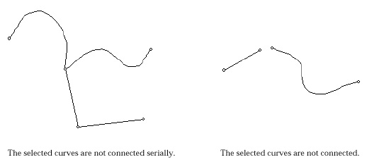
< Example of curves that cannot be linked into a linked curve >
> Separating curves
Linked curves can be separated into individual curves of original state prior to linking. In order to separate linked curves, select them, and choose "Separate" from menu. More than one linked curve can be separated at once.
> Filleting two straight lines
Filleting is used to connect two straight lines with an arc of a specified radius.
In order to continue filleting with other straight lines, repeat 2), 3) and 5) instead of starting from step 1). Filleting can be performed as long as "Fillet" dialog is on the screen. Filleting action can be terminated by closing the dialog or by starting any other tool in the tool palette. Filleting is performed if and only if two straight lines are selected. The two lines do not have to touch in order to preform filleting, but must be capable of intersecting.
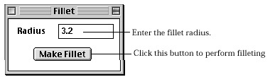
< Fillet dialog >
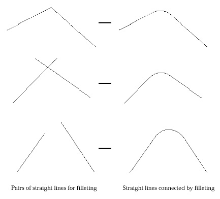
< Examples of filleting >
> Splitting curves by their intersection points
If there are two or more curves crossing with each other, then there are intersection points. You may need split each of them at their intersection points. This can be achieved by the following steps:
| 1) Activate curve selection |
|
| 2) Select curves for intersection. | |
| 3) Choose "Intersect" from |
In case there are one or more divided curves among the selected curves, they are involved in determining the intersection points, but will not be spit. Every segment split from a curve forms an independent curve.
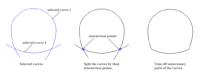
< Example of processing curves using their intersection points >
> Obtaining intersection curves between surface primitives
If there are two or more surface primitives crossing with each other, then there are intersection curves.
| 1) Activate surface primitive selection tool |
|
| 2) Select surface primitives for intersection. | |
| 3) Choose "Intersect" from menu. | |
| A surface primitive can not be split by their intersection curves. But, intersection curves are useful in setting the boundary of mesh region on surface primitives. |
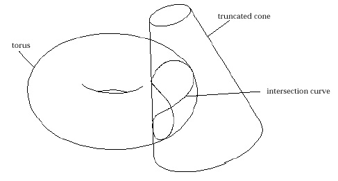
< Example of intersecting surface primitives >
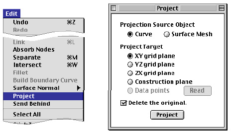
> Projecting curves
New curves may be created by projecting other curves on the specified grid plane.
| 1) Choose "Project" item from |
|
| " P roject" dialog opens. Curves or surface meshes can be projected to the designated target using this dialog. | |
 |
|
| 2) Turn on the radio button "Curve" under "Projection Source Object." | |
| The curve selection tool |
|
| 3) Set the projection target. | |
| There are radio buttons "XY grid plane", "YZ grid plane", "ZX grid plane" and "Construction plane" which represent projection targets. Select one of them. | |
| 4) Select the curves for projection. | |
| When one or more curves are selected, |
|
| 5) Click |
|
| The the selected curves are projected on the target object. |
Nodes as well as control points on the new curves are also formed by projection of corresponding nodes and control points on the mother curves.
> Building boundary curves of a surface primitive
A closed surface such as a sphere or a torus has no boundary curves. But, such an open surface as a cylinder or a cone has boundary curves. These boundary curves may be used in defining the surface region for mesh generation, and should be built for use.
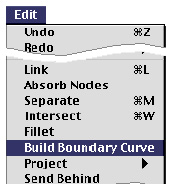 |
1) Activate surface primitive selection tool |
| 2) Select surface primitives, the boundary curves of which are to be generated. | |
| When one or more surface primitives are selected, "Build Boundary Curve" item is enabled. | |
| 3) Choose "Build Boundary Curve" from |
|
| This command is effective only for open surface primitive. Boundary curves are created on all the effective surface primitives. Once the boundary curves are created, they are independent objects which do not belong to the mother primitive surfaces any longer. |
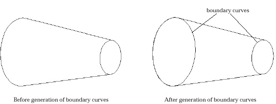
< Building boundary curves of surface primitives >
|
|
|
|