![]()
![]()
![]()
![]()
| Mesh Generation > Surface Mesh Generation > Surface mesh generation by mapping |
|
|
|
|
||
Surface mesh generation by mapping
If 2, 3 or 4 edges are given, a mesh region is formed between or within the edges. VisualFEA supports 3 types of edge formation as follows:
| 2 edges | |
| 3 edges | |
| 4 edges |
The nodal points of the generated mesh are computed by mapping techniques called
"Lofting", "triangular mapping"
or "transfinite mapping" respectively for each
of the above 3 types. These techniques are not explained in detail here. The
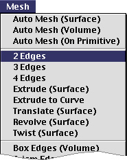
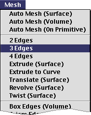
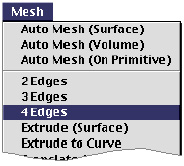
commands generating mesh by mapping are provided as menu items
in ![]() menu.
menu.
> Generating mesh using 2 edges
 |
A surface mesh can be generated using two opposite edges formed by a series of curves. This is the simplest and most frequently used method of mesh generation. The space between the two edges is filled with triangular or quadrilateral elements depending on your choice. The nodes on the mesh are created along the lines connecting two opposite nodes on the edges. |
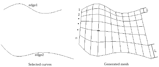
< Example of surface mesh generation between 2 edges >
> Setting 2 edges compatible for mesh generation
For successful 2 edge surface mesh generation, curves should be selected so that they may form 2 edges compatible for mesh generation as described below.
| The selected curves should be connected serially in two groups. This grouping for optimal mesh generation is automatically done by VisualFEA. Each of the two groups forms an edge. Each edge may consist of one or more curves. | |
| The two edges must be separated. They should not contact or cross with each other. | |
| Edges may be open or closed. If one edge is closed, the other edge must also be closed. | |
| Each edge should have an equal number of nodes on it. |
Examples on the following page illustrate mesh regions compatible and incompatible for 2 edge mesh generation.
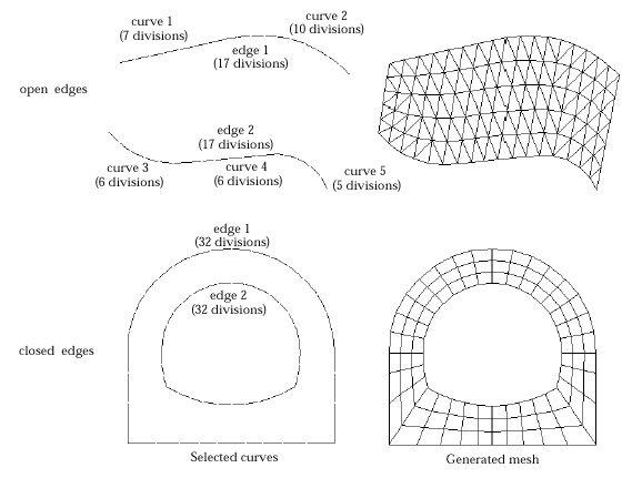
<Examples of 2 edge formation compatible for mesh generation>
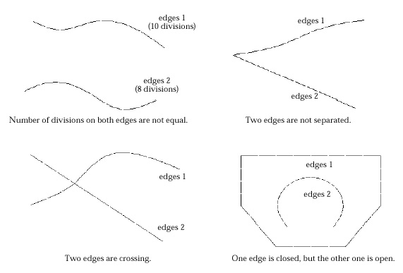
<Examples of 2 edge formation incompatible for mesh generation>
> Shifting alignment of node pairing on 2 edges
If the two edges form closed loops respectively, the one-to-one pairing of
the nodes on the edges are optimally determined by the software. However, it
is rare but possible that the automatic pairing results in generation of elements
with distorted or improper shape. The mesh shape can be improved by manually
adjusting the alignment of the node pairing. This is achieved by pressing ![]() button,
in "2 Edge Surf" dialog, which is enabled when the mesh is generated.
button,
in "2 Edge Surf" dialog, which is enabled when the mesh is generated.
![]() button
is valid only in case both edges form closed loops respectively. There are 7
different alignments, each of which is obtained one after another as the button
is pressed consecutively. The sequence of the alignment is as follows:
button
is valid only in case both edges form closed loops respectively. There are 7
different alignments, each of which is obtained one after another as the button
is pressed consecutively. The sequence of the alignment is as follows:
| 1) The outer loop shifts clockwise. | |
| 2) The inner loop shifts clockwise. | |
| 3) Both the inner loop and the outer loop shift clockwise. | |
| 4) The outer loop shifts counter-clockwise. | |
| 5) The inner loop shifts counter-clockwise. | |
| 6) Both the inner loop and the outer loop shift counter-clockwise. | |
| 7) The initial alignment is obtained again. |
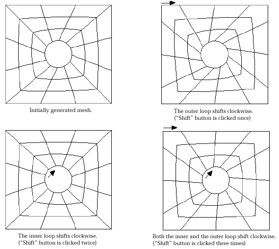
< Example of alignment shifting in looped 2 edges >
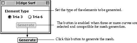
> Generating mesh using 3 edges
 |
A surface mesh can be generated using 3 edges formed by a series of curves. The region enclosed by the 3 edges is filled with triangular elements. The coordinates of the nodes on the mesh are determined by interpolating the nodal points on the 3 edges using triangular mapping technique. The region is mapped with an equilateral triangle. Therefore, the 3 edges should be formed in the configuration of a triangle. |
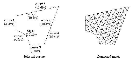
< Example of surface mesh generation enclosed by 3 edges >
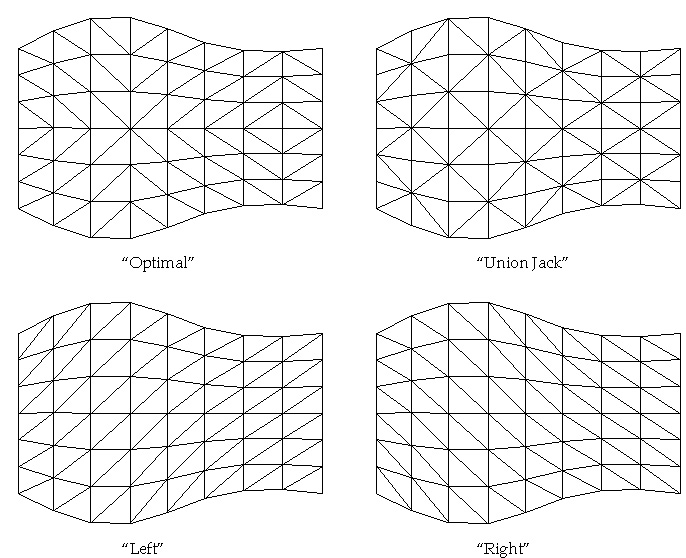
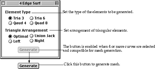
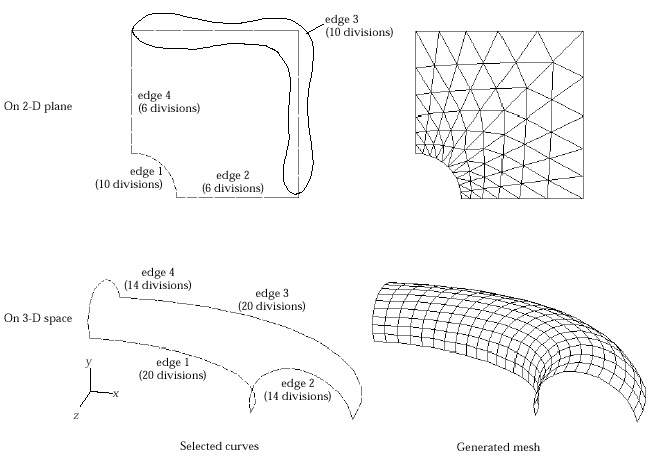
> Generating mesh using 4 edges
 |
A surface mesh can be generated using 4 edges formed by a series of curves. The region enclosed by the 4 edges is filled with triangular or quadrilateral elements depending on your choice. The coordinates of the nodes on the mesh are determined by interpolating the nodal points on the 4 edges using transfinite mapping technique. The region is mapped with a square. There f o re, the 4 edges should be formed in the configuration of a quadrangle. |
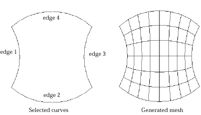
< Example of surface mesh generation enclosed by 4 edges >
> Setting 4 edges compatible for mesh generation
For successful 4 edge surface mesh generation, curves should be selected so that they may form 4 edges compatible for mesh generation as described below.
| The selected curves should be connected serially to form a closed loop with 4 edges. | |
| The 4 edges may be regarded as boundary lines of a quadrilateral region with two pairs of edges facing opposite to each other. | |
| Each pair of edges should have an equal number of nodes on them. | |
| Edges are constructed automatically by VisualFEA so that each pair of edges have equal number of nodes on them. If such construction is not possible, mesh generation is aborted after a message ˇ°Incompatible curve selection for 4 edge surface.ˇ± | |
| All the internal angles of vertexes made by two adjacent edges should be less than 180 . | |
| Even if this condition is not met, a mesh may be generated. But the generated mesh will have improper shape and will trespass outside of the mesh region |
The following examples illustrate compatible and incompatible selection of curves
<Examples of 4 edge formation compatible for mesh generation>
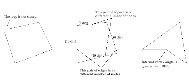
<Examples of 4 edge formation incompatible for mesh generation>
|
|
|
|