Surface mesh generation by sweeping operations
VisualFEA supports the following 4 types of sweeping operations which may be
used for surface mesh generation:
| |
Extrusion |
| |
Translation |
| |
Revolution |
| |
Twisting |
Sweeping creates a surface mesh by traversing the seed curves along a path
defined in space. The sweeping operations, i.e., extrusion, translation, revolution,
and twisting are distinguished by the characteristics of their sweeping path.
The sweeping path for extrusion is a single straight line. Any continuous curve
passing through, or meeting at the seed curve, may be used as the path for translation.
The paths for revolution are circles with their centers along the axis
of revolution. Twisting uses helical path for mesh generation. The commands
for surface mesh generation by sweeping are provided as menu items in  menu.
menu.
> Generating mesh by extrusion
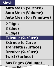 |
A surface mesh can be generated by extruding
selected curves up to the specified height and in the specified direction.
The height of the extrusion is entered using the "Extr Surf" dialog. |
| |
1) Choose "Extrude(Surface)" from
menu.
|
| |
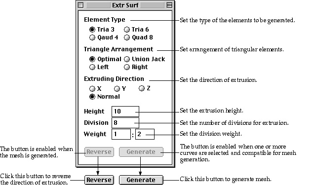
The curve selection tool  is
automatically activated, and "ExtrSurf" dialog box appears. is
automatically activated, and "ExtrSurf" dialog box appears. |
| |
 |
| |
2) Set the element type. |
| |
Choose one of the 4 element types given as radio buttons in
the dialog. |
| |
3) Select the type of arrangement for triangular elements.
|
| |
The triangular elements can be generated in the 4 different
types of arrangement as explained in the previous section "Generating
mesh using 2 edges" |
| |
4) Set the direction of extrusion. |
| |
The mesh may be extruded either in the direction of a coordinate
axis, or in the direction normal to the seed curve. The normal direction
is determined independently at each of the extruding nodes on the seed curve. |
| |
5) Enter the height of extrusion. |
| |
Extrusion height is the distance from the seed curve to the
extent of the mesh generation. |
| |
6) Enter the number of divisions for extrusion. |
| |
Specify how many rows of elements to be generated by extrusion. |
| |
7) Enter the weight of division density. |
| |
Enter the weight of division density in the form of w1:wn
, which is the ratio between width of elements at the starting part and
at the ending part of extrusion. |
| |
8) Select curves forming seed curves for extrusion. |
| |
All the selected curves should be divided, and form an edge,
which may be one curve or serially connected curves. The edge may be either
open or closed.  button
is enabled when an edge is formed properly for mesh generation. button
is enabled when an edge is formed properly for mesh generation. |
| |
9) Click  button. button.
|
| |
A surface mesh is generated by extruding the seed curve, if
the selected curves are compatible for mesh generation. Otherwise, the action
is ignored after a message "Incompatible curve selection for extrusion."
|
At this stage, even if the cycle ended with failure, button
is disabled as it should be at step 2).  button
is enabled, only when mesh generation is successful. In case the mesh is generated
opposite to the desired direction, click
button
is enabled, only when mesh generation is successful. In case the mesh is generated
opposite to the desired direction, click  button
to revert the direction of extrusion. Then, mesh will be regenerated with the
reverse direction. You may repeat the above procedure of generating mesh by
extrusion without issuing the command again, while "Extr Surf" dialog
remains on the screen. This mesh generation command is terminated by closing
the dialog box or issuing any other command.
button
to revert the direction of extrusion. Then, mesh will be regenerated with the
reverse direction. You may repeat the above procedure of generating mesh by
extrusion without issuing the command again, while "Extr Surf" dialog
remains on the screen. This mesh generation command is terminated by closing
the dialog box or issuing any other command.
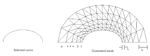
< A surface mesh generated by extrusion in normal direction
>
The direction of extrusion is not necessarily in the same plane as the seed
curve. Extrusion can be used effectively in creating 3-dimensional surface mesh
by extruding the seed curve out of its plane as shown in the example below.
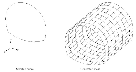
< A 3-D surface mesh generated by extrusion in an out-of-plane
direction >
> Generating mesh by extrusion up to bounding curves
 |
Instead of specifying the height of extrusion,
you may define the bound of the extrusion by selected curves. These curves
are termed here as "bounding curve." This method of mesh generation
is the same as the above described extrusion method except that the extent
of extrusion is determined not by its height but by the bounding curves.
The advantage of this method is that the direction of extrusion as well
as the boundary of the mesh can be controlled. |
| |
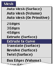
1) Choose "Extrude to Curve" from
menu.
|
| |
The curve selection tool is
automatically activated, and "Extr to Curve" dialog box appears. |
| |
 |
| |
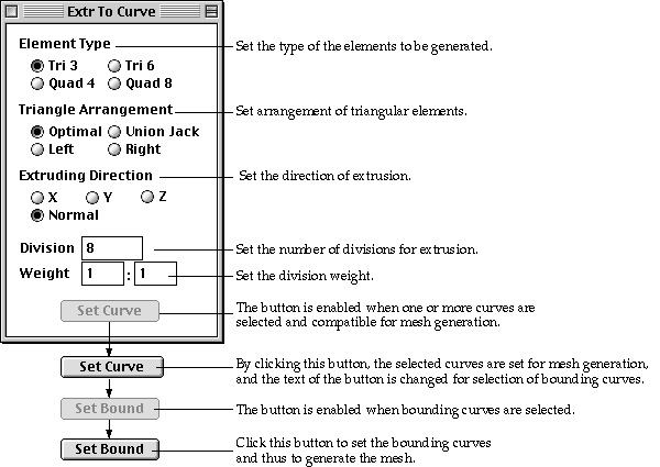
2) Set the element type. |
| |
Choose one of the 4 element types given as radio buttons in
the dialog. |
| |
3) Select the type of arrangement for triangular elements.
|
| |
The triangular elements can be generated in the 4 diff e rent
types of arrangement as explained in the previous section "Generating
mesh using 2 edges". |
| |
4) Set the direction of extrusion. |
| |
The mesh may be extruded either in the direction of a coordinate
axis, or in the direction normal to the seed curve. The direction is always
signed toward the bounding curves. |
| |
If both the seed curves and the bounding curves are closed,
normal direction is the only option that can generate valid mesh by extrusion. |
| |
5) Set the number of divisions for extrusion. |
| |
Specify how many rows of elements are to be generated by extrusion. |
| |
6) Set the weight of division density. |
| |
Enter the weight of division density in the form of w1:wn
, which is the ratio between width of elements at the starting part and
at the ending part of extrusion. |
| |
7) Select curves forming seed curves for extrusion. |
| |
All the selected curves should be divided, and form an edge,
which may be one curve or serially connected curves.  button
is enabled when an edge is formed properly for mesh generation. button
is enabled when an edge is formed properly for mesh generation. |
| |
8) Click  button. button.
|
| |
The selected curves are reserved as the seed curves for mesh
generation, and the button changes into  indicating
that selection of bounding curves is expected in the next step. indicating
that selection of bounding curves is expected in the next step. |
| |
9) Select the bounding curves. |
| |
The selected bounding curves are highlighted in bright red
color. The dimmed button
is enabled when bounding curves are selected. |
| |
10) Click  button. button.
|
| |
A mesh is generated by extruding the seed curves up to the
bounding curves. button
is restored to button.
It is now ready for generating another surface mesh. |
| |
The bounding curve should be closed if the seed curve is
closed, and should be open otherwise. If the bounding curves are open, they
must be long enough to cover the whole range of extrusion. Otherwise, the
mesh generation will be aborted with a message, ˇ°Insufficient coverage of
the bounding curve.ˇ± |
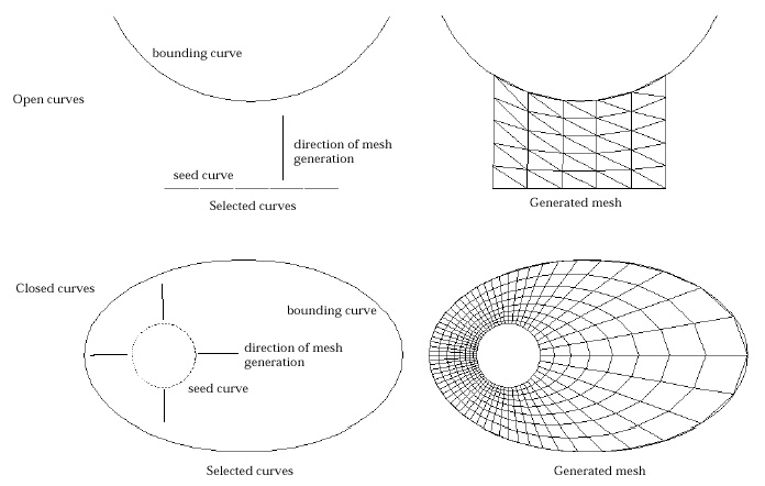
<Mesh generated by extrusion up to bounding curves>
You may repeat the above procedure of mesh generation without issuing the command
again, while "Extr to Curve" dialog remains on the screen. This mesh
generation command is terminated by closing the dialog box or issuing any other
command.
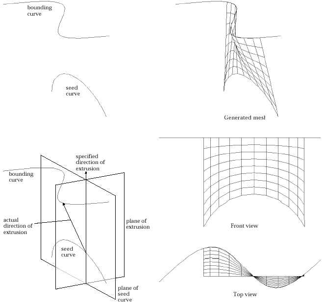
< Determination of extruding direction in case the seed curve
and the bounding curve are not on the same plane >
> Generating mesh by translation
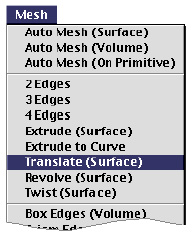 |
A surface mesh can be generated by translating
the selected seed curves along the specified sweeping
path. The boundaries of the generated elements are defined by a set of curves
parallel to the seed curves and the other set parallel to the sweeping path.
The previously described method of mesh generation by extrusion may be regarded
as a special case of this operation in which the sweeping path is a straight
line drawn in the specified direction. |
| |
1) Choose "Translate(Surface)" from menu.
|
| |
The curve selection tool is
automatically activated, and "Translate Surf " dialog box appears. |
| |
 |
| |
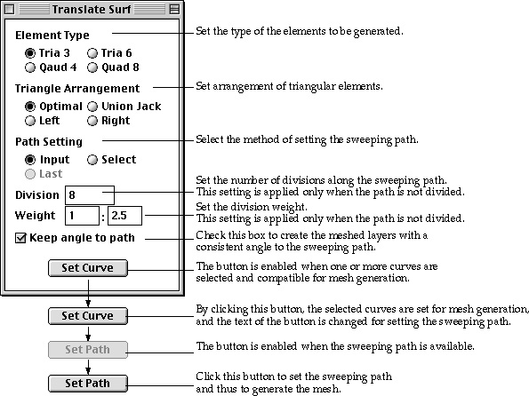
2) Set the element type. |
| |
Choose one of the 4 element types given as radio buttons in
the dialog. |
| |
3) Select the type of arrangement for triangular elements.
|
| |
Triangular elements can be generated in the 4 different types
of arrangement as explained in the previous section "Generating mesh
using 2 edges". |
| |
4) Select the option for path setting. |
| |
Choose one of the 3 options setting the sweeping path, "Input",
"Select" and "Last" by clicking the corresponding radio
button. The "Last" button is enabled only when this method of
mesh generation was applied at least once since the dialog box appeared. |
| |
5) Set the number of divisions for translation. |
| |
Specify how many rows of elements are to be generated by translation.
This setting is applied only when the sweeping path is not divided. If divided
curves are selected as the sweeping path, their divisions will be applied
regardless of this setting. |
| |
6) Check or uncheck "Keep angle to path" check box.
|
| |
If this check box is checked, the meshed layers are created
so that they have a constant angle with the sweeping path. Otherwise, all
the layers are made parallel. |
| |
7) Set the weight of division density. |
| |
Enter the weight of division density in the form of w1:wn
, which is the ratio between width of elements at the starting part and
at the ending part of translation. This setting is also applied only when
the sweeping path is not divided. |
| |
8) Select curves forming seed curves for translation. |
| |
All the selected curves should be divided, and form an edge,
which may be one curve or serially connected curves. The seed curves may
be open or closed. button
is enabled when an edge is formed properly for mesh generation. |
| |
9) Click button.
|
| |
The selected curves are reserved as the seed curves for mesh
generation, and the button changes into  indicating
that setting the sweepin path is expected in the next step. indicating
that setting the sweepin path is expected in the next step. |
| |
10) Set the sweeping path. |
| |
Set the sweeping path by the method selected at step 4). |
| |
|
"Input " : If the method is set as "Input"
one of the curve input tool is activated, and the cursor changes into shape.
And, it is now ready for creating a sweeping path by inputting a new curve.
At this step, line tool button is activated so that straight lines may be
entered. Any type of curves may be used as the sweeping path. In order to
input desired types of curves, click the corresponding curve tool button. |
| |
|
"Select" : If the method is set as "Select"
the curve selection tool is activated, and thus cursor changes into shape.
Select a curve which will be used as the sweeping path. Either divided or
undivided curves are acceptable. |
| |
|
"Last" : The sweeping path for last mesh generation
is applied again. So, it is not necessary to input or select the sweeping
path. This option can be used only when this method of mesh generation was
applied at least once since the dialog box appeared. |
| |
|
The sweeping path should be open, and its one end point
should meet with a node on the seed curve. The sweeping path may be one
curve or serially connected curves. If the sweeping path consists of more
than one curve, they must be either all divided or all undivided. Mixed
use of divided and undivided curves for sweeping path is not allowed. |
| |
11) Click button. |
| |
A mesh is generated by translating the seed curves along the
sweeping path. button is restored to button. It is now ready for generating
another surface mesh. The curve selection tool i s automatically activated,
if it is not in action. |
You may repeat the above procedure of mesh generation without
issuing the command again, while "Translate Surf" dialog remains on
the screen. This mesh generation command is terminated by closing the dialog
box or issuing any other command.
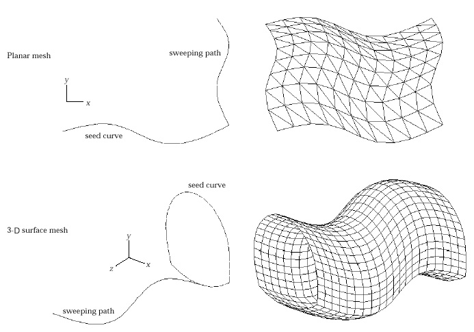
< Example of mesh generation by translation on plane and
in 3-D space>
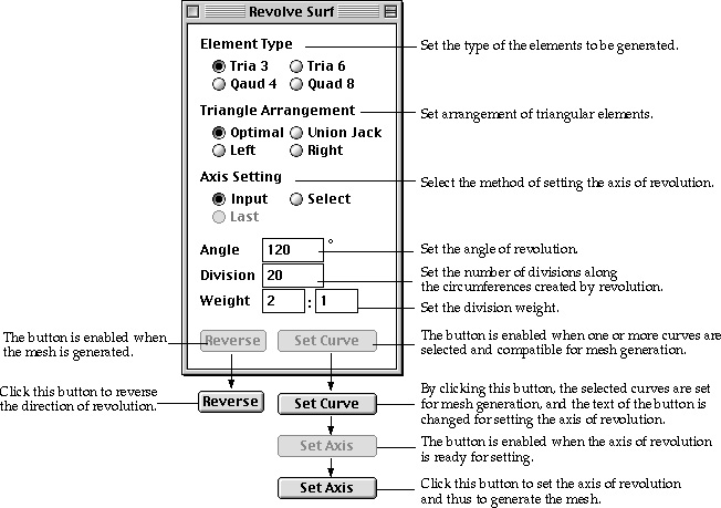
> Generating mesh by revolution
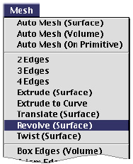 |
Curved surface elements are generated on the
surface of revolution created by revolving seed curves about the specified
axis. The latitude and the longitude of the surface form the boundaries
of the generated elements. The axis of revolution may be set interactively
in any desired direction. Either a partial or a full surface of revolution
is created depending on the specified angle. The direction of revolution
can be reversed if necessary. |
| |
1) Choose "Revolve (Surface)"
from menu.
|
| |
The curve selection tool is
automatically activated, and "Revolve Surf " dialog box appears. |
| |
 |
| |
2) Set the element type. |
| |
Choose one of the 4 element types given as radio buttons
in the dialog. |
| |
3) Select the type of arrangement for triangular elements.
|
| |
The triangular elements can be generated in the 4 diff e
rent types of arrangement as explained in the previous section "Generating
mesh using 2 edges" |
| |
4) Select the option for setting the axis of revolution.
|
| |
Choose one of the 3 options setting the axis of revolution,
"Input", "Select" and "Last" by clicking the
corresponding radio button. The "Last" button is enabled only
when this method of mesh generation was applied at least once since the
program started. |
| |
5) Set the angle of revolution. |
| |
Insert the angle of revolution in the dialog box. The angle
should be greater than or equal to -360 and less than equal to 360
. Both -360 and 360 makes full surface of revolution. The negative
sign reverses the direction of revolution. |
| |
6) Set the number of divisions for revolution. |
| |
Specify how many rows of elements are to be generated by
revolution in circumferential direction. |
| |
7) Set the weight of division density. |
| |
Enter the weight of division density in the form of w1:wn
, which is the ratio between width of elements at the starting part and
at the ending part of revolution. |
| |
8) Select curves forming seed curves for revolution. |
| |
All the selected curves should be divided, and form an edge,
which may be one curve or serially connected curves. The seed curves may
be open or closed. button
is enabled when an edge is formed properly for mesh generation. |
| |
9) Click button.
|
| |
The selected curves are reserved as the seed curves for mesh
generation, and the button changes into  indicating
that setting the axis of revolution is expected in the next step. indicating
that setting the axis of revolution is expected in the next step. |
| |
10) Set the axis of revolution. |
| |
Set the axis of revolution by the method selected at step
4). |
| |
|
"Input" : If the method is set as "Input"
the line tool button is automatically activated, and the cursor changes
into shape. Input the axis of revolution following the same procedure as
that of creating a straight line. |
| |
|
"Select" : If the method is set as
"Select" the curve selection tool is activated, and thus cursor
changes into shape. Select a straight line which will be used as the axis
of revolution. |
| |
|
"Last" : The axis of revolution for
last mesh generation is applied again. So, it is not necessary to input
or select the axis. This option can be used only when this method of mesh
generation was applied at least once since the program started. |
| |
|
The sweeping path should be open, and its one end point
should meet with a node on the seed curve. The sweeping path may be one
curve or serially connected curves. If the sweeping path consists of more
than one curve, they must be either all divided or all undivided. Mixed
use of divided and undivided curves for sweeping path is not allowed. |
| |
11) Click  button. button.
|
| |
A mesh is generated by revolving the seed curves about the
axis of revolution. button
is restored to button.
The program is now ready for generating another surface mesh. The curve
selection tool is
automatically activated, if it is not in action. button
is enabled, only when mesh generation is successful. Clicking button
reverses the sign of the revolution angle and regenerates the mesh. |
You may repeat the above procedure of mesh generation without issuing the command
again, while "Revolve Surf" dialog remains on the screen. This mesh
generation command is terminated by closing the dialog box or issuing any other
command.
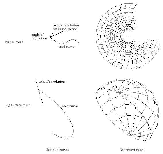
< Example of mesh generation by revolution in a plane and
in 3-D space>
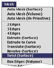
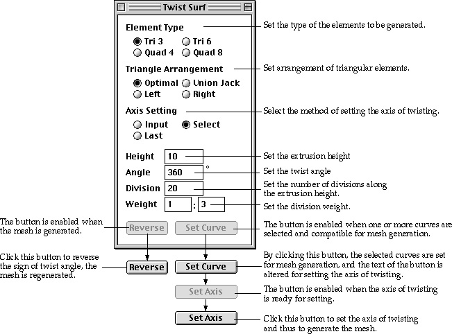
> Generating mesh by twisting
 |
Twisting is a method of mesh generation by extrusion
combined with revolution. So, it may be termed as "Twisted
extrusion." Elements are generated on the surface which is formed by
extruding the selected seed curves along the specified axis while twisting
the direction of extrusion about the axis by the specified angle. Along
this twisted extrusion, the trace of a node on the seed curve makes a helix
on which new nodes are created. If the twist angle is set to zero, the resulting
mesh generation is identical to that of extrusion in the direction of the
twist axis. Likewise, if the extrusion height is set to zero, a surface
mesh of revolution is obtained. This method of mesh generation is useful
in modeling curved surfaces of spiral shape. |
| |
1) Choose "Twist (Surface)" from menu.
|
| |
The curve selection tool is
automatically activated, and "Twist Surf" dialog box appears. |
| |
 |
| |
2) Set the element type. |
| |
Choose one of the 4 element types given as radio buttons
in the dialog. |
| |
3) Select the type of arrangement for triangular elements. |
| |
Triangular elements can be generated in the 4 different types
of arrangement as explained in the previous section "Generating mesh
using 2 edges" |
| |
4) Select the option for setting the twist
axis. |
| |
Choose one of the 3 options setting the twist axis, "Input",
"Select" and "Last" by clicking the corresponding radio
button. The "Last" button is enabled only when this method of
mesh generation was applied at least once since the program started. |
| |
5) Set the extrusion height. |
| |
Insert the extrusion height in the dialog box. The direction
of extrusion is given by that of the twist axis which is directed from the
first input point to the second. |
| |
6) Set the twist angle. |
| |
Insert the twist angle in the dialog box. There is no limit
in the acceptable range of twist angle. The negative sign reverses the direction
of twist. |
| |
7) Set the number of divisions. |
| |
Specify how many rows of elements are to be generated in
the direction of the twisted extrusion. |
| |
8) Set the weight of division density. |
| |
Enter the weight of division density in the form of w1:wn
, which is the ratio between width of elements at the starting part and
at the ending part of twisting. |
| |
9) Select curves forming seed curves for twisting. |
| |
All the selected curves should be divided, and form an edge,
which may be one curve or serially connected curves. The seed curves may
be open or closed. button
is enabled when an edge is formed properly for mesh generation. |
| |
10) Click button.
|
| |
The selected curves are reserved as the seed curves for mesh
generation, and the button changes into indicating
that setting the twist axis is expected in the next step. |
| |
11) Set the twist axis. |
| |
Set the twist axis by the method selected at step 4). |
| |
|
"Input" : If the method is set as "Input"
the line tool button is automatically activated, and the cursor changes
into shape. Input the twist axis following the same procedure as that of
creating a straight line. |
| |
|
"Select" : If the method is set as
"Select" the curve selection tool is activated, and thus cursor
changes into shape. Select a straight line which will be used as the twist
axis. |
| |
|
"Last" : The twist axis for last mesh
generation is applied again. So, it is not necessary to input or select
the axis. This option can be used only when this method of mesh generation
was applied at least once since the program started. |
| |
12) Click button.
|
| |
A mesh is generated by twisted extrusion of the seed curve.
button
is restored to button.
The program is now ready for generating another surface mesh. The curve
selection tool is automatically activated, if it is not yet activated. button
is enabled, only when mesh generation is successful. Clicking button
reverts sign of the twist angle and regenerates the mesh. |
You may repeat the above procedure of mesh generation without issuing the command
again, while "Twist Surf" dialog remains on the screen. This mesh
generation command is terminated by closing the dialog box or issuing any other
command.
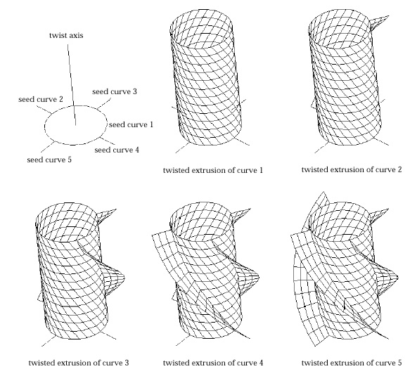
< Example of modeling 3-D surfaces by twisting>