![]()
![]()
![]()
![]()
| Mesh Generation > Volume Mesh Generation > Volume mesh generation by mapping |
|
|
|
|
||
Volume mesh generation by mapping
An analysis region may be represented by its boundary edges. Volume meshes are generated to fill the region formed by the boundary edges. VisualFEA supports following 3 types of edge formation for volume mesh generation:
The "Triangular mapping" and "Transfinite mapping" techniques
applied to surface mesh generation are also extended for volume mesh generation
in 3-dimensional regions defined by the above 3 types of edge formation. The
new nodal points in the generated mesh are computed by these mapping techniques.
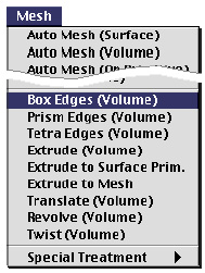
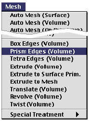
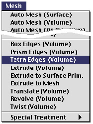
The mesh generation commands are provided as menu items in ![]() menu.
menu.
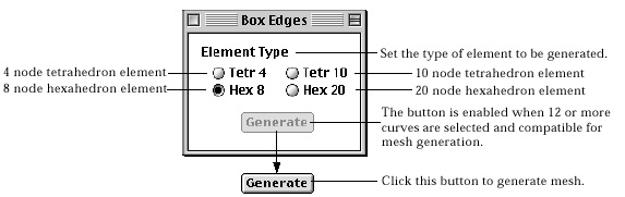
> Generating mesh using box edges
 |
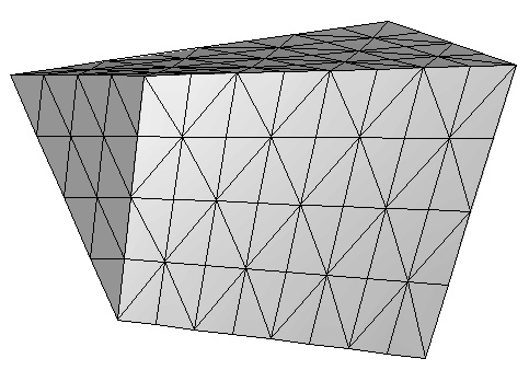
A volume mesh can be generated using transfinite mapping technique in a box-shaped region bounded by 12 edges, each of which consists of a curve or serially connected curves. The shape of the elements within the mesh may be chosen from tetrahedron and hexahedron. Prism elements are not included because they may cause incompatibility between adjacent mesh regions. |
You may repeat the above procedure of generating mesh using 12 edges without issuing the command again, while "Box Edges" dialog remains on the screen. This mesh generation command is terminated by closing the dialog box or issuing any other command.
< Example of mesh generation in a box edge region >
> Setting box edges compatible for mesh generation
For successful mesh generation by this method, curves should be selected so
that they may form 12 edges compatible for box edge mesh generation as described
below. When ![]() button
is clicked at step 4 in the above procedure , VisualFEA checks if selected curves
fulfill these conditions. When the curves selections are acceptable, the mesh
generation procedure is processed.
button
is clicked at step 4 in the above procedure , VisualFEA checks if selected curves
fulfill these conditions. When the curves selections are acceptable, the mesh
generation procedure is processed.
| The selected curves should be connected serially in 12 groups. This grouping is automatically done by VisualFEA. Each of the 12 groups forms an edge. Each edge may consist of one or more curves. | |
| The 12 edges must have configurations equivalent to edges of a box. For this requirement, 3 edges must meet at each of the 8 corner points of the box. There should be no edges with open ends. In other words, each edge should be connected to other edges at both ends. | |
| The number of nodes on each group of parallel edges must be equal. Edges 1, 2, 3 and 4 are parallel in the above example. Likewise, edges 5, 6, 7 and 8,and edges 9, 10, 11 and 12 are parallel edges respectively. | |
| For element types "Tetra 4" and "Hexa 20" each edge should be divided in multiples of 2. And for "Tetra 10" each edge should be divided in multiples of 4. | |
| For compatibility of element boundaries between adjacent mesh regions, the tetrahedron elements of a box edge region are generated so that triangular faces in the outer surfaces should have Union Jack formation as shown in the figure below. Accordingly, each of the 12 edges should be divided into multiples of 2 in order to generate í░Tetra 4í▒, and into multiples of 4 in order to generate í░Tetra 10í▒. If this condition does not meet when you try generating these types of elements, the action will not be processed. |
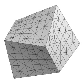
<Formation of Union Jack on surfaces of a box edge volume mesh>
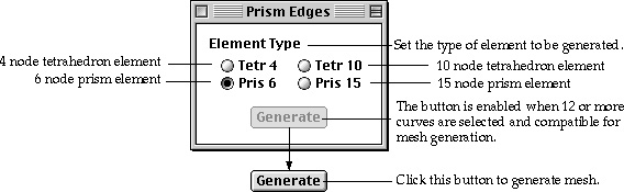
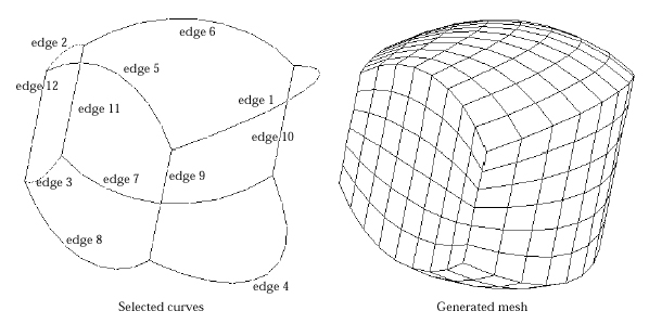
> Generating mesh using prism edges
 |
A volume mesh can be generated in a prism-shaped region bounded by 9 edges, each of which consists of a curve or serially connected curves. The shape of the elements within the mesh may be chosen from tetrahedron and prism. For mesh generation, transfinite mapping is applied in the longitudinal direction of the prism and triangular mapping on the triangular sections. |
You may repeat the above procedure of generating mesh using 9 edges without issuing the command again, while "Box Edges" dialog remains on the screen. This mesh generation command is terminated by closing the dialog box or issuing any other command.
< Example of mesh generation in a prism edge region >
> Setting prism edges compatible for mesh generation
For successful mesh generation by this method, curves should be selected so
that they may form 9 edges compatible for prism edge mesh generation as described
below. When ![]() button
is clicked at step 4 in the above procedure , VisualFEA checks if selected curves
fulfill these conditions. Only when the curves selections are acceptable, the
mesh generation procedure is processed.
button
is clicked at step 4 in the above procedure , VisualFEA checks if selected curves
fulfill these conditions. Only when the curves selections are acceptable, the
mesh generation procedure is processed.
| The selected curves should be connected serially in 9 groups. This grouping is automatically done by VisualFEA. Each of the 9 groups forms an edge. Each edge may consist of one or more curves. | |
| The 9 edges must have configurations equivalent to edges of a prism. For this requirement, 3 edges must meet at each of the 6 corner points of the box. There should be no edges with open ends. | |
| The number of nodes on the edges forming triangular faces must be equal. Edge 1, 2 and 3 forms a triangular face, and edge 4, 5 and 6 form another. The number of nodes on the edges forming longitudinal faces should also be equal. That is, the number of nodes on edge 7, 8 and 9 must not be different. | |
| For element types "Tetra 4" and "Prism 15" each edge should be divided in multiples of 2. And for "Tetra 10" each edge should be divided in multiples of 4. | |
| For compatibility of element boundaries between adjacent mesh regions, the tetrahedron elements of a prism edge region are generated so that triangular faces in the longitudinal surfaces should have Union Jack formation as shown in the figure below. Accordingly, each of the 9 edges should be divided into multiples of 2 in order to generate í░Tetra 4í▒, and into multiples of 4 in order to generate í░Tetra 10.í▒ If this condition does not meet when you try generating these types of elements, the action will not be processed. |
<Formation of Union Jack on surfaces of a prism edge mesh>
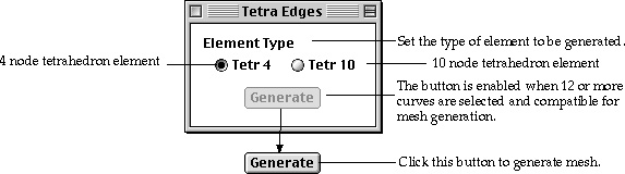
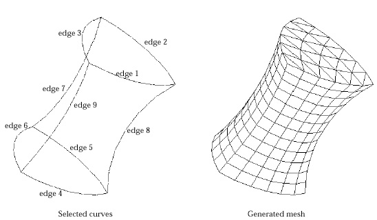
> Generating mesh using tetrahedron edges
 |
A volume mesh can be generated in a tetrahedron-shaped region bounded by 6 edges, each of which consists of a curve or serially connected curves. The shape of the elements generated by this method is always tetrahedron. For mesh generation, triangular mapping is applied on every triangular section of the tetrahedron. |
You may repeat the above procedure of generating a mesh using 6 edges without issuing the command again, while "Tetra Edges" dialog remains on the screen. This mesh generation command is terminated by closing the dialog box or issuing any other command.
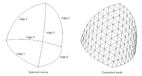
< Example of mesh generation in a tetra edge region >
> Setting tetra edges compatible for mesh generation
For successful mesh generation by this method, curves should be selected so
that they may form 9 edges compatible for tetra edge mesh generation as described
below. When ![]() button
is clicked at step 4 in the above procedure , VisualFEA checks if selected curves
fulfill these conditions. Only when the curves selections are acceptable is
the mesh generation procedure processed.
button
is clicked at step 4 in the above procedure , VisualFEA checks if selected curves
fulfill these conditions. Only when the curves selections are acceptable is
the mesh generation procedure processed.
| The selected curves should be connected serially in 6 groups. This grouping is automatically done by VisualFEA. Each of the 6 groups forms an edge. Each edge may consist of one or more curves. | |
| The 6 edges must have configurations equivalent to edges of a tetrahedron. For this requirement, 3 edges must meet at each of the 4 corner points of the box. There should be no edges with open ends. | |
| The number of nodes on all the edges forming triangular faces must be equal. | |
| For element types "Tetra 10" each edge should be divided in multiples of 2. |
|
|
|
|