![]()
![]()
![]()
![]()
| Mesh Generation > Volume Mesh Generation >Volume mesh generation by sweeping operations |
|
|
|
|
||
Volume mesh generation by sweeping operations
VisualFEA supports the following 4 types of sweeping operations for volume
mesh generation:
| Extrusion | |
| Translation | |
| Revolution | |
| Twisting |
Sweeping operations for volume mesh generation are analogous to those for surface
mesh generation explained in the previous section. Refer to "Surface mesh
generation by sweeping operations." For volume mesh generation, sweeping
operations are based on selected surfaces, i.e. seed surfaces while surface
mesh generation is based on seed curves. The commands for volume mesh generation
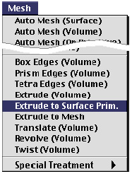
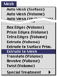
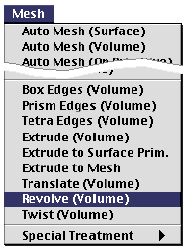
by sweeping are provided as menu items in ![]() menu.
menu.
In case of volume mesh generation by sweeping, the type of element is determined by the type of element on the seed surfaces as shown below. Therefore, it is not necessary to set the type of the element.

< Element types in the seed mesh and in the generated volume mesh >
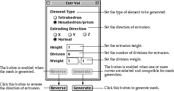
> Generating mesh by extrusion
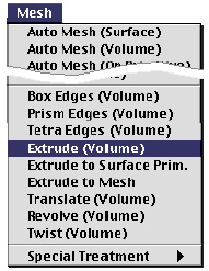 |
A volume mesh can be generated by extruding the seed surfaces up to the specified height and in the specified direction. The height of the extrusion is entered using the "Extrude" dialog. This is the simplest but most frequently used method of generating volume meshes. There are three methods generating a volume mesh by extruding seed surfaces. The other 2 methods are explained in the following sections. |
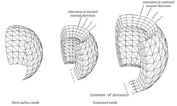
< A volume mesh generated by extrusion in normal direction >
> Generating mesh by extrusion up to bounding surface primitives
| 1) Choose "Extrude to Surface Prim." from |
|
| The surface selection tool |
|
 |
|
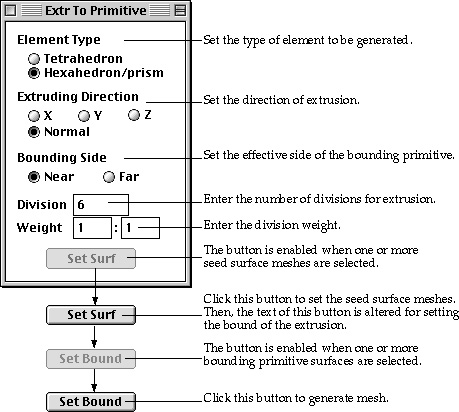
| 2) Set the element type. | |
| If the element shape of the seed mesh is triangle, either tetrahedron or prism elements can be generated. Otherwise, only hexahedron elements can be generated, and thus this step is not necessary. | |
| 3) Set the direction of extrusion. | |
| The mesh may be extruded either in the direction of a coordinate axis, or in the direction normal to the seed surface. The direction is always signed toward the bounding surface primitive. | |
| 4) Set the side of the bound. | |
| There are usually more than two sides of the bounding surfaces applicable as the boundary of the generated mesh. Therefore, it is necessary to specify which side of the bounding primitives should be applied. | |
| 5) Set the number of divisions for extrusion. | |
| Specify how many layers of elements to be generated by extrusion. | |
| 6) Set the weight of division density. | |
| Enter the weight of division density in the form of w1:wn , which is the ratio between thickness of elements at the starting part, l1 and at the ending part of extrusion, ln. | |
| 7) Select surface meshes forming seed surfaces for extrusion. | |
| |
|
| 8) Click |
|
| The selected surface meshes are reserved as the seed surfaces
for mesh generation, and the button changes into |
|
| 9) Select the bounding surface primitives. | |
| The selected bounding primitives are highlighted in bright
red color. The dimmed |
|
| 10) Click |
|
| A mesh is generated by extruding the seed meshes up to the
bounding primitives. button is restored to |
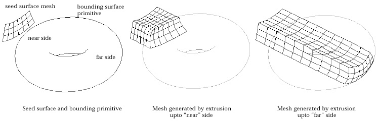
< Example of mesh generation by extrusion to a surface primitive >
> Generating mesh by extrusion up to surface meshes
 |
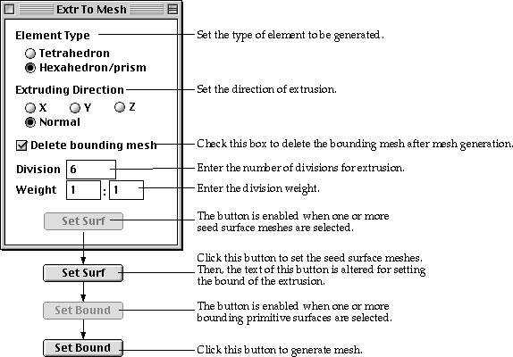
The bound of the extrusion may be specified by surface meshes. This method of mesh generation is useful when the bound of extrusion is a f ree-form surface which cannot be expressed by surface primitives supported in VisualFEA. These surface meshes are termed here as "Bounding mesh." This method of mesh generation is the same as the above described method of "Extrusion up to surface primitives" except that surface meshes instead of bounding primitives are used as the bounding limit. In order to apply this method, the bounding surface mesh should be generated before starting the process of mesh generation. |
| 1) Choose "Extrude to Mesh" from |
|
| The surface selection tool |
|
 |
|
| 2) Set the element type. | |
| If the element shape of the seed mesh is triangle, either tetrahedron or prism elements can be generated. Otherwise, only hexahedron elements can be generated, and thus this step is not necessary. | |
| 3) Set the direction of extrusion. | |
| The mesh may be extruded either in the direction of a coordinate axis, or in the direction normal to the seed surface. The direction is always signed toward the bounding surface meshes. | |
| 4) Specify whether to delete the bounding mesh automatically after mesh generation. | |
| In most cases, the only usage of the bounding mesh is to generate the volume mesh by this method. Then it is desirable to delete the bounding meshes after the mesh generation. If "Selete bounding mesh" box is checked, the bounding mesh will be deleted automatically when the mesh is generated. Otherwise, the bounding meshes remain undeleted after mesh generation. | |
| 5) Set the number of divisions for extrusion. | |
| Specify how many layers of elements to be generated by extrusion. | |
| 6) Set the weight of division density. | |
| Enter the weight of division density in the form of w1:wn , which is the ratio between thickness of elements at the starting part, l1 and at the ending part of extrusion, ln. | |
| 7) Select surface meshes forming seed surfaces for extrusion. | |
| |
|
| 8) Click |
|
| The selected surface meshes are reserved as the seed surfaces
for mesh generation, and the button changes into |
|
| 9) Select the bounding surface meshes. | |
| The selected bounding meshes are highlighted in bright red
color. The dimmed |
|
| If the bounding surface is flat, its density does not affect the result of the mesh generation. But, in case the bounding surface is curved, the smoothness of generated mesh may be affected by its density. Higher density is required in order to represent curved surfaces more accurately. | |
| 10) Click |
|
| A volume mesh is generated by extruding the seed meshes up
to the bounding meshes. |
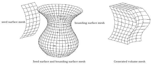
< Example of mesh generation by extrusion to a surface mesh>
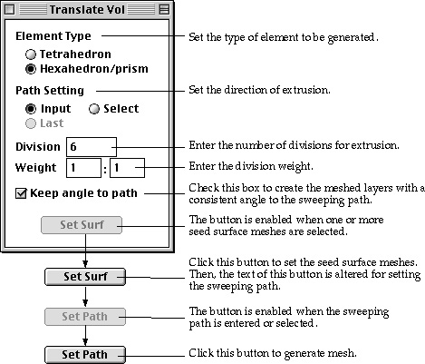
> Generating volume mesh by translation
 |
A volume mesh can be generated by translating the selected seed meshes along the specified sweeping path. Every node on the seed meshes makes a trace parallel to the sweeping path. New nodes are created along these traces, and all of them are contained in the newly generated mesh. This method is useful in modeling curved structural members with uniform section. In applying this method, some care should be taken not to make a self-interfering mesh. |
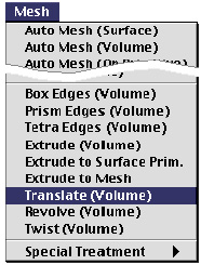
| 1) Choose "Translate (Volume)" from |
|
| The surface selection tool |
|
 |
|
| 2) Set the element type. | |
| If the element shape of the seed mesh is triangle, either tetrahedron or prism elements can be generated. Otherwise, only hexahedron elements can be generated, and thus this step is not necessary. | |
| 3) Select the option for path setting. | |
| Choose one of the 3 options setting the sweeping path, "Input", "Select" and "Last" by clicking the corresponding radio button. The "Last" button is enabled only when this method of mesh generation was applied at least once since the dialog box appeared. | |
| 4) Set the number of divisions for translation. | |
| Specify how many rows of elements to be generated by translation. This setting is applied only when the sweeping path is not divided. If divided curves are selected as the sweeping path, their divisions will be applied regardless of this setting. | |
| 5) Set the weight of division density. | |
| Enter the weight of division density in the form of w1:wn , which is the ratio between width of elements at the starting and at the ending part of the curve. | |
| 6) Check or uncheck "Keep angle to path" check box. | |
| If this check box is checked, the meshed layers are created so that they have a constant angle with the sweeping path. Otherwise, all the layers are made parallel. | |
| 7) Select surface meshes for seed meshes. | |
| |
|
| 8) Click |
|
| The selected surfaces are reserved as the seed meshes for
mesh generation, and the button changes into |
|
| 9) Set the sweeping path. | |
| Set the sweeping path by the method selected at step 3). Tools corresponding to the method are automatically activated, and the cursor changes accordingly. The sweeping path should be open, and its one end point should meet with a node on the seed curve. The sweeping path may be one curve or serially connected curves. If the sweeping path consists of more than one curve, they must be either all divided or all undivided. Mixed use of divided and undivided curves for sweeping path is not allowed. | |
| 10) Click |
|
| A mesh is generated by translating the seed meshes along
the sweeping path. |

< Example of volume mesh generation by translation >
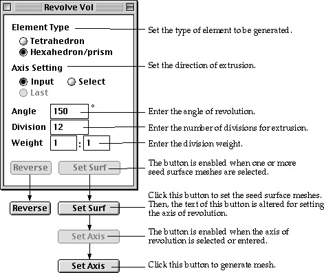
> Generating volume mesh by revolution
 |
A solid of revolution is generated by revolving seed surfaces about the specified axis. Volume elements are created within a ring formed by revolving each of the surface element on the seed mesh. The axis of revolution may be set interactively in any desired direction. The revolution may be full or partial depending on the specified angle. The direction of revolution can be reversed if necessary. |
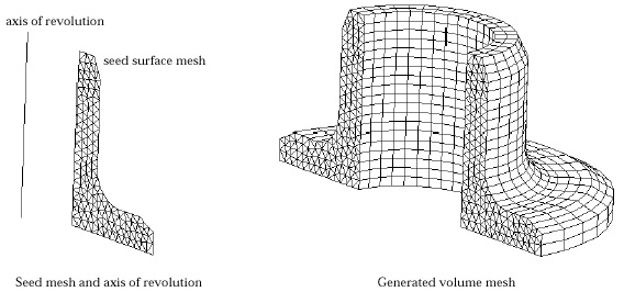
< Example of volume mesh generation by revolution >
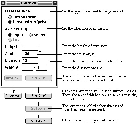
> Generating volume mesh by twisting
 |
Twisting is a method of mesh generation by extrusion combined with revolution. So, it may be termed as "Twisted extrusion" Elements are generated on the surface which is formed by extruding the selected seed curves along the specified axis while twisting the direction of extrusion about the axis by the specified angle. Along this twisted extrusion, the trace of a node on the seed curve makes a helix on which new nodes are created. |
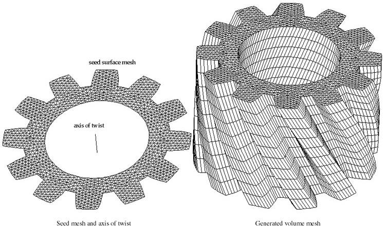
< Example of modeling 3-D solid by twisting>
|
|
|
|