![]()
| Data Assignment > Structural Element Properties > Using interface elements |
|
|
|
|
||
Using interface elements
Interface elements are used in modeling the behavior of gaps with negligible width. They cannot be used alone, but may be included in plane stress, plane strain or axisymmetric problems. (The current version of VisualFEA supports only 2 dimensional interface elements.)
> Characteristics of interface elements
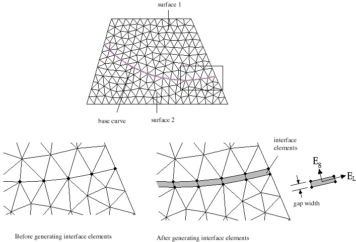
Interface elements fill the gap separating two adjacent surfaces. They connect the nodes on the boundaries of both surfaces. VisualFEA supports only 4 node interface elements. The structural behavior of the gap can be controlled by the stiffness of the interface elements in width and length directions. These stiffness are determined by the moduli of elasticity in both directions, and the gap width of the elements. A pair of nodes facing with each other are separated by as much as the specified gap width. Assigning zero or very small value of gap width or large modulus of elasticity in width direction will restrain the relative movement in width direction, of the pair of nodes. On the other hand, the modulus of elasticity in length direction controls the relative movement in length direction. So, you may model the desired behavior of the gap, or relative movement of the contacting surfaces by assigning appropriate values to the properties of interface elements.

< Characteristics of interface elements >
> Creating interface elements
Interface elements are created somewhat differently from other structural types of elements. They are not created by mesh generation or curve input, but by assignment of element properties as explained below.
|
1) Choose "Interface" item from the popup menu in "Property" dialog. |
||
|
The data items in "Property" dialog are altered. |
||
|
2) Enter the value for each data item. |
||
|
The interface element can be made to represent specific behavior by entering appropriate values for the data items. |
||
|
modulus of elasticity in length direction |
||
|
modulus of elasticity in gap width direction |
||
|
gap width (gap): The width of interface of elements. This value should be small as compared with the dimension of the whole structure. |
||
|
thickness (t): This item is applicable only for plane stress problems. Usually, this value is set as identical to the thickness of the main structure in which the interface elements are embedded. |
||
|
3) Select one or more base curves to assign interface elements. |
||
|
The selected base curves are to be used as the basis of the interface elements. Therfore, they should be serially connected, and completely embedded within the main structure. |
||
|
4) Click |
||
|
Interface elements are created on the selected curves. The active set of element properties are assigned to the newly created elements. When interface elements are created, the basis curves together with the nodes on them are duplicated. The interface elements are composed of the nodes on the new and existing base curves. |
||

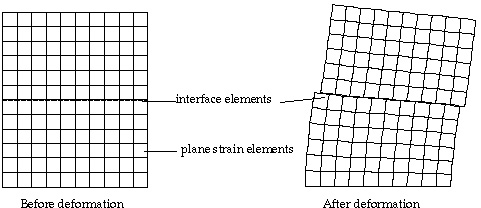
< Example of a plane strain case with interface elements >
> Deleting interface elements
Interface elements can be deleted only by deleting the set of element property assigned to them. The meshes are restored to the state before creating interface elements. That is, the surface meshes separated by the interface elements are joined
|
|
|
|