![]()
| Data Assignment > Heat Conduction and Seepage Properties > Seepage properties |
|
|
|
|
||
 |
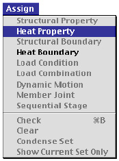
If the analysis subject is defined as a seepage problem, "Seepage Property" item appears in menu and is enabled. Choose the item in order to start assigning seepage properties. "Property" dialog appears, and the current state of their assignment are displayed in the main window. |
> Defining seepage properties
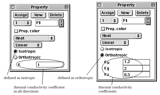
Seepage properties include the hydraulic conductivity coefficients in X and Y directions for 2-D seepage problems, and in X, Y and Z directions for 3-D seepage problems. The conductivity can be re p resented by one value for isotropic material as shown in the figure below. Check "Isotropic" radio button to input the conductivity coefficients as isotropic material. Seepage properties include conductivity functions for unconfined seepage analysis. The conductivity function defines the ratio of the reduced conductivity to the full conductivity as a function of pore pressure.

> Defining hydraulic conductivity functions
A conductivity function is associated with each one of the seepage property
sets. Click ![]() button
in the "Property" dialog to input a conductivity function for the
current property set. Then, "Hydraulic Conductivity Function" dialog
appears on the screen. The conductivity function can be defined either by equation
or by table using this dialog as described below.
button
in the "Property" dialog to input a conductivity function for the
current property set. Then, "Hydraulic Conductivity Function" dialog
appears on the screen. The conductivity function can be defined either by equation
or by table using this dialog as described below.
|
1) Click |
|
|
The dialog opens with default settings. The dialog consists of 2 parts as shown in the figure below. The first part is used to define the hydraulic conductivity function by an equation, and the other part to define the function in tabular form. |
|
|
|
|
|
2) Turn on "Define by equation" radio button to define the conductivity function by an equation. |
|
|
The hydraulic conductivity factor c is computed as a function of negative pore pressure P by the equation, |
|
|
|
|
|
where a is the Gardner coefficient and n is a power factor. |
|
|
The conductivity factor implies the ratio of the reduced conductivity in negative pore pressure region to the full conductivity. |
|
|
3) Insert the Gardener coefficient a, and power factor n. |
|
|
The value of a is normally assumed between 0.001 and 0.1, and the value of n between 2 and 4. |
|
|
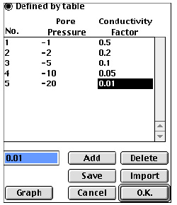
4) Turn on "Define by table" radio button to define the conductivity function in tabular form. |
|
|
The hydraulic conductivity is defined by the tabulated relation between the pore pressure and the conductivity factor. The conductivity factor is computed by linear interpolation of the given pore pre s s u res and the conductivity factors. |
|
 |
|
|
5) Click |
|
|
The buttons are enabled when "Defined by table" radio button is turned on. After creating a new row, insert the values of the row using the editable text box. |
|
|
6) Click |
|
|
The "Hydraulic Conductivity Function" dialog closes, and the conductivity function is added to the current seepage property set. The check box of "Conductivity Func." item of the "Property" dialog is marked to indicate that the hydraulic function of the property set is defined. |
> Assigning seepage properties
In order to assign seepage properties, first select the object to assign, and
click ![]() button
of the "Property" dialog. Seepage properties can be assigned only
to surface meshes in the case of plane and axisymmetric seepage problems, and
only to volume meshes in the case of 3-D seepage problems.
button
of the "Property" dialog. Seepage properties can be assigned only
to surface meshes in the case of plane and axisymmetric seepage problems, and
only to volume meshes in the case of 3-D seepage problems.
|
|
|
|