![]()
| Data Assignment > Structural Boundary Conditions > Defining structural boundary conditions |
|
|
|
|
||
Defining structural boundary conditions
You must first create and define sets of boundary conditions before assigning them on the structural boundaries. All the data items of the active set are displayed on "Struct Boundary" dialog and can be entered or modified using the dialog.
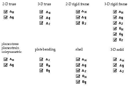
The boundary condition dictates the state of each nodal degree of freedom. The nodal d.o.f. differ depending on the subject of analysis. If more than one structural type is involved in the analysis, the items are extended to hold all associated structural types.

< Nodal d.o.f for various analysis subjects >
> Data items of structural boundary condition
A structural boundary condition set has a few data items. They consist of nodal fixity, initial displacements or spring constants defined for each d.o.f.

< Nodal d.o.f for various analysis subjects >
> Entering data items of boundary conditions
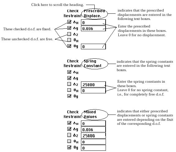
The fixity of each nodal d.o.f. is entered by clicking the check box in front of the symbol indicating the respective d.o.f. The prescribed displacements and the spring constants are entered within the corresponding text boxes. As shown below, not all the text boxes are displayed. Some of them are hidden. Displayed items are related to the heading of the text items. There are 3 headings:
| " Prescribed Displace" : This heading indicates that only text items for p rescribed displacements are shown. Because displacements can be prescribed only for fixed d.o.f., the text items of fixed d.o.f. are displayed. | |
| "Spring Constant" : This heading indicates that only text items for spring constants are shown. Because spring constants can be applied only for free d.o.f., the text items of free d.o.f. are displayed. | |
| "Fixed Values" : This heading indicates that text items for spring constants as well as for prescribed displacement are shown. Thus, all text items are displayed. The heading is initially set as "Prescribed Displace." You may scroll through the above three headings by clicking any point over the heading. But, only applicable ones will be scrolled. For example, if non-zero values are entered in pre scribed displacements, "Spring Constant" will be skipped. |

< Headings of editable text items >
> Defining boundary conditions in local coordinates
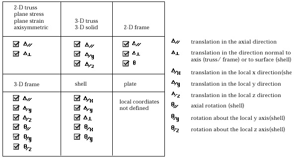
The structural boundary conditions can be defined in either in global coordinates or in local coordinates. The local coordinates are based on the axis of a structural member, the tangent direction of a surface edge, or the normal to a surface. Check "Local direction" box of "Struct Boundary" dialog in order to use local coordinates for a boundary condition set. At the moment, the "Local direction" is checked, the d.o.f. labels are altered as shown in the figure below.

< Boundary constraints in local coordinates >
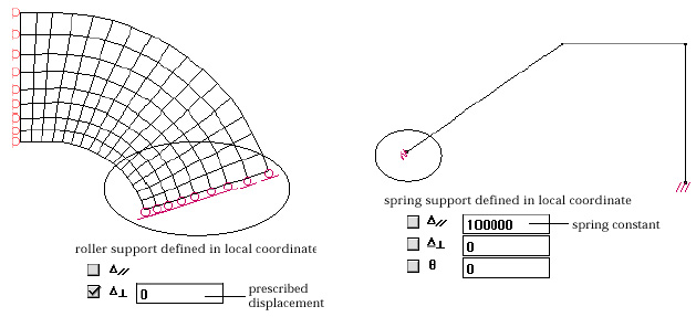
Use of local coordinates may be most appropriate for roller support and spring boundary condition which are illustrated in the figure below. The prescribed displacements and the spring constants are entered for the local coordinates in the same way as for the global coordinates.

< Examples of boundary conditions defined in local coordinates >
In most cases, only the axial direction or the normal direction is concerned with the boundary conditions in local coordinates. The axial and normal directions at every node is determined in association with the object to which the boundary condition is assigned.
| curve: In the case the boundary condition is assigned to a
curve, the axial (//) direction is defined as tangent to the curve at every
node on the curve. For planar models, the normal (^) direction is uniquely
determined from the axial direction. For 3-D models, the 2 normal (/y and
/z) directions are determined by vector operations of the unit axial vector |
|
 |
|
| where |
|
| surface mesh: In the case the boundary condition is assigned
to a surface mesh, the normal direction (^) is first determined at every
node on the surface mesh. And the 2 other (/x and /y) directions are determined
by vector operations of the unit normal vector and the unit vector |
|
 |
|
| where |
|
|
node: If the node belongs to only one curve or only one surface mesh, the normal or the axial direction is determined by the curve and the surface. But, if the node shared by multiple curves or by multiple surfaces, then the program asks to choose the curve or the surface mesh to be used as the basis for determining the local directions. |
|
 |
|
|
First, choose one of the two ratio buttons, "Set the tangent curve",
or "Set the tangent surface mesh. (For a frame or a planar problem,
the second button is dimmed, and the first button is turned on.) And select
the curve or the surface mesh for the basis of the local directions. Then,
|
|
|
|
|