![]()
| Data Assignment > Structural Boundary Conditions > Assigning structural boundary conditions |
|
|
|
|
||
Assigning structural boundary conditions
The structural boundary conditions are assigned to objects as a set. The currently
active set is assigned to selected objects by clicking ![]() button
of the dialog. It is assumed that all the nodes are initially free. That is,
none of the nodal d.o.f. are constrained fully or partially at the beginning.
Assigning a boundary condition set is equivalent to modifying the unconstrained
state of each nodal d.o.f. Thus, the boundary condition sets are assigned only
to the nodes, one or more d.o.f of which are fixed or free with spring constant.
It is meaningless to define or assign a boundary condition set with all d.o.f.
free. If you define such a set and assign it to the selected objects, the assignment
is ignored.
button
of the dialog. It is assumed that all the nodes are initially free. That is,
none of the nodal d.o.f. are constrained fully or partially at the beginning.
Assigning a boundary condition set is equivalent to modifying the unconstrained
state of each nodal d.o.f. Thus, the boundary condition sets are assigned only
to the nodes, one or more d.o.f of which are fixed or free with spring constant.
It is meaningless to define or assign a boundary condition set with all d.o.f.
free. If you define such a set and assign it to the selected objects, the assignment
is ignored.
> Selecting objects to assign structural boundary conditions
S t ructural boundary conditions may be assigned to nodes, curves and surface
meshes. However, the data sets are eventually assigned to nodes within the objects.
For example, assigning a boundary condition set to a surface mesh is equivalent
to assigning the set to all nodes within the surface mesh. For a 3 dimensional
solid, boundary conditions are usually assigned only to the outer surfaces,
or to nodes on these surfaces. Therefore, it is sometime necessary to prevent
assigning boundary conditions to nodes inside the volume inadvertently. This
can be done by checking "Shut Invisible Nodes" item in ![]() menu
so that the inside nodes become unselectable.
menu
so that the inside nodes become unselectable.
> Replacing or adding previous assignment
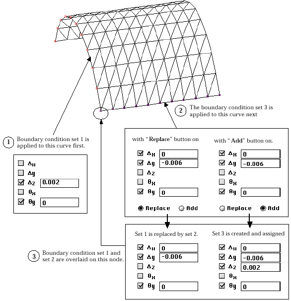
When a new structural boundary condition set is assigned to a node with previously assigned boundary conditions, the old set will be either replaced by or added to the new one, depending on the mode of overlaying data sets. In "Struct Boundary" dialog, there are two radio buttons, "Replace" and "Add" If "Replace" button is on, the old assignment is replaced by the new assignment. The text data items are also replaced by the corresponding values of the new set. If "Add" button is on, the resulting assignment is the union of the old and the new assignments. The state of a d.o.f. is determined by bit ORing with '0' for free d.o.f. and '1' for fixed d.o.f. If the editable text data of both old and new sets are of same kind( both prescribed displacements or both spring constants), the item is filled with the one whose absolute value is larger. If there exists a boundary condition set identical to the one resulting from the bit ORing, that set is assigned to the node with the overlaid boundary conditions. Otherwise, a new set is created.

< Example of overlaying boundary conditions >
> Representation of boundary condition assignment
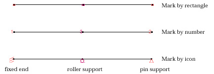
Nodal assignment of structural boundary conditions is re p resented by icon,
number or rectangle marked at the node. Choose the desired option of marking
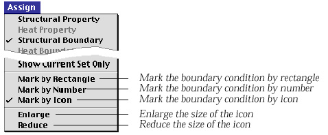
the boundary conditions from ![]() menu.
The item of the currently applied option is checked as shown below. The icon
option is available only for 2-D modeling.
menu.
The item of the currently applied option is checked as shown below. The icon
option is available only for 2-D modeling.


<Options of representing boundary conditions>
If a boundary condition set is assigned to curves or surfaces,
the individual nodes on the curves or surfaces are marked. The nodes assigned
with the currently active data set are highlighted in dark red, and the nodes
with other sets are marked in bright red. The boundary conditions are displayed
only when "Sruct Boundary" dialog is on the screen. Check "Show
Str. Boundary" item of ![]() menu
to make the boundary conditions displayed even when "Struct Boundary"
dialog is not on. The size of the icon representing the boundary conditions
can be enlarged or reduced by using "Enlarge" or "Reduce"
item of
menu
to make the boundary conditions displayed even when "Struct Boundary"
dialog is not on. The size of the icon representing the boundary conditions
can be enlarged or reduced by using "Enlarge" or "Reduce"
item of ![]() menu.
menu.
|
|
|
|