![]()
| Data Assignment > Structural Boundary Conditions > Seepage boundary conditions |
|
|
|
|
||
If the analysis subject is set as either "2-D Seepage", "Axisymmetric Seepage", or "3- D Seepage", the text of the menu item "Heat Boundary" changes to "Seepage Boundary". Selection of the menu item pops up the "Seepage Boundary" dialog. Seepage boundary conditions can be defined and assigned, while the dialog is on the screen,

> Types of seepage boundary condition
There are a few different types of seepage boundary conditions as described below:
> Assigning open head boundary condition
Open head boundary conditions can be assigned using "Seepage Boundary" dialog by the following procedure.
|
1) Set the popup menu (Windows: dropdown list) to "Open Head". |
|
|
2) Insert the value of the water head in the editable text box with label "H". |
|
|
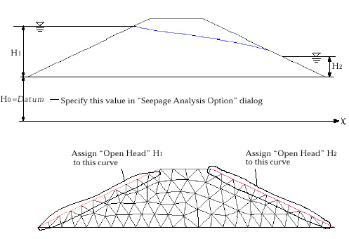
The upstream water level H1 and the downstream water level H2 a re the values of the open water heads in the example below. |
|
|
The water levels are measured from the datum to be specified in "Analysis Option" dialog. Refer to "Setting analysis options for seepage analysis" section of Chapter 6. |
|
|
3) Select the boundary curves or surfaces to be assigned with the open head.. |
|
|
Select curves for 2-D analysis and surfaces for 3-D analysis. |
|
|
4) Assign the boundary condition to the selected objects by clicking
|

<Example of open head boundary conditions>
> Assigning confined head boundary condition
As an alternative to the open head boundary condition in the above example, the nodes of the upstream edge under the water level can be assigned with "Confined Head" H1, because the nodes of the upstream edge cannot form a phreatic water face above the upstream water level. However, it should be noted that the confined head should assigned only to the nodes under the upstream water level.

<Example of a confined head boundary condition in unconfined seepage analysis>
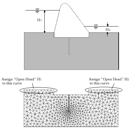
The above example is to show that a confined boundary condition may substitute an open head boundary condition in some cases. But confined boundary conditions are commonly used to prescribes the constant head at the selected nodes or nodes along the selected curve, as shown in the example below. In the case of confined seepage analysis, only confined head conditions are applied. In order to assign confined head boundary conditions, set the popup menu(Windows : dropdown list) to "Confined Head," and follow the similar procedure as that of open head boundary condition.

<Example of confined head conditionsion confined seepage analysis>
> Assigning flux
Water supply or drain through the boundary surfaces is re p resented by the boundary condition of flux. In order to assign fluxes, set the popup menu(Windows: dropdown list) to "Flux". The value of the flux should re p resent volume of water per unit area per unit time. The flux should be assigned to boundary curves in 2-D seepage analysis and to boundary surfaces in 3-D seepage analysis.
> Assigning point source
Water supply or drain at a point is represented by the boundary condition of point source. In o rder to assign point sources, set the popup menu(Windows: dropdown list) to "Point Source". The value of the point source should re p resent volume of water per unit time. The point source should be assigned to nodes.
> Defining the initial water table
In transient analysis, the initial water table should be defined as the phreatic surface at the initial stage. But in steady state analysis, the initial water table can be considered as the initially assumed phreatic water surface, and therefore, defining the initial water table may not be essential. However, the assumption of the initial water table affects the computational efficiency of the iterative solution process, and is essentially used in obtaining the overall distribution of the negative pore water pressure above phreatic surface. The negative pore water pressure above the initial water table is set to 0. The initial water table can be defined by the following procedure.
|
1) Create a curve or a surface to be defined as the initial water table. |
|
|
The initial water table is defined by one or more curves in 2-D seepage analysis, and one or more surface meshes in 3-D seepage analysis. The curves or surface meshes can be created as usual. If there already exist curves or surface meshes that can be defined as the initial water table, this step can be ignored. |
|
|
2) Open "Seepage Boundary" dialog if it is not yet opened. |
|
|
3) Set the popup menu (Windows: dropdown list) to "Initial Water Table". |
|
|
4) Select the curves or the surface meshes to be defined as the initial water table. |
|
|
5) Click |

<Example of initial water table>
|
|
|
|