![]()
| Data Assignment > Load Conditions > Defining load condition sets |
|
|
|
|
||
Defining load condition sets
Load conditions are defined and assigned by the data unit called a load condition
set. A load condition set is initially created by clicking ![]() button
of "Load Condition" dialog. If a load set is already assigned, additional
assignment of the set, either to a single object or multiple objects, creates
a new load set automatically by duplicating the set. Loads applied to the assigned
object(s) share the new load set.
button
of "Load Condition" dialog. If a load set is already assigned, additional
assignment of the set, either to a single object or multiple objects, creates
a new load set automatically by duplicating the set. Loads applied to the assigned
object(s) share the new load set.
> Data items of a load condition
A set consists of many data items including the type, the direction, the magnitude, and the position of a force. The actual data items vary depending on the type of analysis.
> Load types
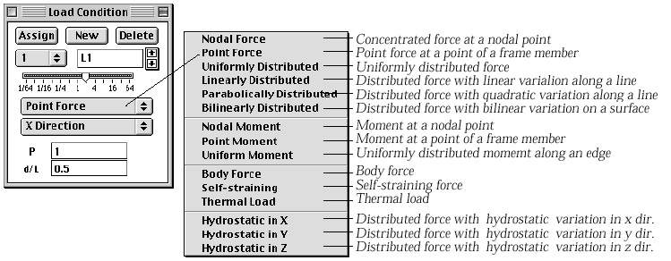
There are a number of different load types as shown in the the popup menu items. Some of the menu items are enabled, while others are disabled depending on the type of analysis. For example, "Point Force" item is available only for 2-D or 3-D frames.
| nodal force: Nodal forces are applied at nodes. When this
item is chosen in the popup menu, the node selection |
|
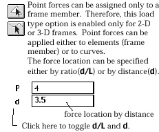
| point force: Point forces are applied at a point between nodes
on a frame member. This item is enabled only for 2-D and 3-D frame analysis.
When this item is chosen in the popup menu, the element selection tool |
|
| uniformly distributed: These are forces distributed uniformly
over a curve or a surface. In order to apply uniform forces, you must first
activate the curve selection tool |
|
| linearly distributed: These are distributed forces with linear
variation along a curve. When this item is chosen in the popup menu, the
curve selection tool |
|
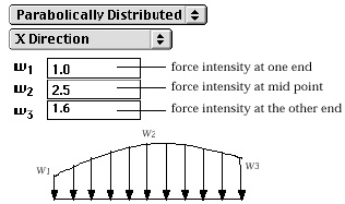
| parabolically distributed: These are distributed forces with
quadratic variation along a curve. When this item is chosen in the popup
menu, the curve selection tool |
|
|
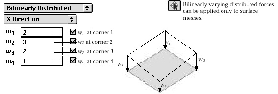
bilinearly distributed: These distributed forces have bilinear variation
on a surface. The force intensity at a point is determined by bilinear
interpolation of the intensities at 4 corner points. When this item is
chosen in the popup menu, the curve selection tool |
|
|
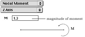
nodal moment: This re p resents a moment or a couple applied at a node. When this item is chosen in the popup menu, the node selection tool is automatically activated. |

< Examples of load types >
|
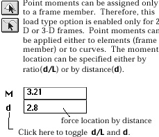
point moment: This re p resents a moment or a couple applied at a point
between nodes on a frame member. This item is enabled only for 2-D and
3- D frame analysis. When this item is chosen in the popup menu, the element
selection tool |
|
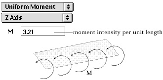
| uniform moment: This re p resents a line moment applied uniformly on a frame member or an edge of a surface. | |
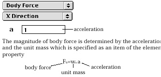
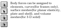
| body forc e: This is the force due to acceleration of mass. One example of body force is the weight, or gravitational force of an object. Body force is applicable to all types of objects except slip bar and embedded bar elements. | |
| self-straining force: This is internally exerted force due to prestressing, lack of fit, and so on. Self-straining force can be applied to frame members or embedded bar elements. | |
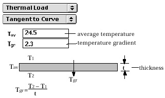
| thermal load: Thermal load implies the temperature variation or temperature gradient which causes strains and stresses. The equivalent nodal forces are computed from the give temperature distribution. In a coupled analysis of structure and heat conduction, the temperature distribution is not specified by the thermal load but is given by the nodal values computed from heHat conduction analysis. | |
|
hydrostatic in X: "Hydrostatic in X" implies linear variation in the X d i rection. This is to re p resent forces distributed on an area with intensity varying linearly in X direction and uniform in other directions. |
|
|
hydrostatic in Y: "Hydrostatic in Y" implies linear variation in the Y d i rection. This is to re p resent forces distributed on an area with intensity varying linearly in Y direction and uniform in other directions. |
|
|
hydrostatic in Z: "Hydrostatic in Z" implies linear variation in the Z direction. This is to represent forces distributed on an area with intensity varying linearly in Z direction and uniform in other directions. |
> Load direction
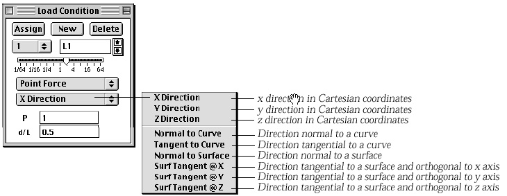
The direction of forces may be specified either in X, Y, and Z axis of Cartesian coordinates system or in local directions normal or tangential to curves or surfaces.
|
X direction: X direction in XYZ coordinate system. |
|
|
Y direction: Y direction in XYZ coordinate system. |
|
|
Z direction: Z direction in XYZ coordinate system. |
|
|
normal to curve: Direction normal to the curve on which the force is acting. |
|
|
tangent to curve: Direction tangential to the curve on which the force is acting. |
|
|
< Direction of a uniform load applied to a curve > |
|
| normal to surface: Direction normal to the surface on which the force is acting. | |
|
tangent to surface and normal to X: The direction tangential to the surface on which the force is acting, and normal to X direction. The direction tangential to a surface is not unique. The direction is constrained to be normal to X direction, so that it became unique. |
|
|
tangent to surface and normal to Y: The direction tangential to the surface on which the force is acting, and normal to Y direction. |
|
|
tangent to surface and normal to Z: The direction tangential to the surface on which the force is acting, and normal to Y direction. |
|
|
no direction: This item is provided only for a thermal load which does not have a direction. The load direction popup item automatically turns to this item when the current load type is set as thermal load. |
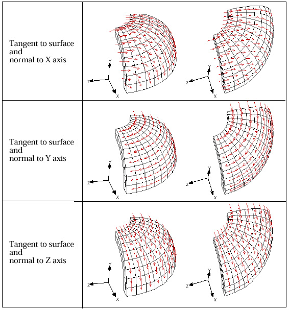
< Directions tangent to surface >
> Editable text items
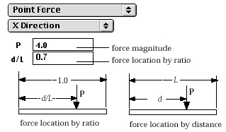
The editable text items are different depending on the type of loads as shown in the following figures. When the popup menu item of load type is selected, corresponding editable text items appear on the dialog. The numerical values related to a force are specified by these editable text items.
< Editable text items of load conditions >
|
Editable Text Items
|
Assignable Object Types
|
 |
 |
 |
 |
 |
 |
 |
 |
 |
 |
 |
|
 |
 |
 |
 |
 |
 |
 |
 |
 |
 |
 |
 |
 |
 |
|
|
|
|