![]()
![]()
![]()
![]()
| Data Assignment > Load Conditions > Other functions related with assigning load conditions |
|
|
|
|
||
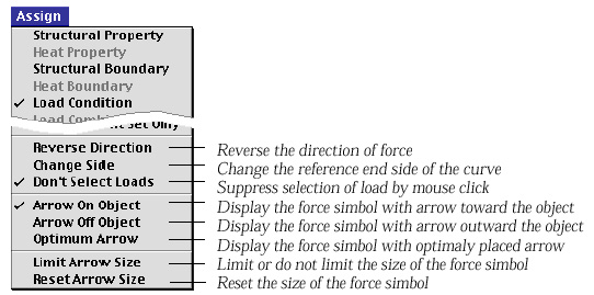
Other functions related to assigning load conditions
Load conditions can be defined and assigned while the load condition dialog
appears on the screen. At this time, the few menu items related with load conditions
are attached to ![]() menu
as shown below.
menu
as shown below.
> Reversing the force direction
The direction of the force can be reversed by simply choosing the item "Reverse
Direction" from ![]() menu.
The force direction of the current load condition set is reversed, and accordingly,
the corresponding editable text items of "Load Condition" dialog is
altered with reversed sign. If a load condition set is applied to multiple objects,
and "Reverse Direction" command is issued immediately, then the direction
of all the lastly assigned loads will be reversed.
menu.
The force direction of the current load condition set is reversed, and accordingly,
the corresponding editable text items of "Load Condition" dialog is
altered with reversed sign. If a load condition set is applied to multiple objects,
and "Reverse Direction" command is issued immediately, then the direction
of all the lastly assigned loads will be reversed.
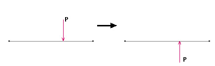
< Result of "Reverse Direction" command>
> Exchanging the reference end of the curve
The location of point force is represented by the distance from one end of
a curve or a frame element. In this case, the starting point of distance is
the reference end of the curve or the element. The magnitude of trapezoidal
force is represented by two load intensity W1 and W2. The end point with W1
may be the reference point . It is sometimes necessary to switch the reference
point. This can be done simply choosing the menu item "Change
Side" from ![]() menu.
menu.
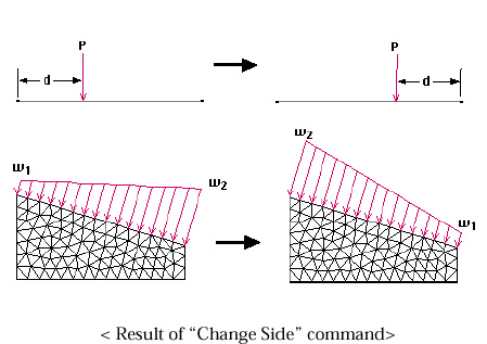
< Result of "Shange Side" command>
Loads can be selected simply by clicking their symbols. You may sometimes annoyed by unintentionally selecting loads instead of other objects which you actually want to select. This may happen especially when many load symbols are densely located at the point of mouse click. Under such situation, it is convenient to suppress the selection of loads temporarily. Suppressing and desuppressing can be toggled by choosing "Don't Select Loads" item from menu. The current state is indicated by the check mark in front of the menu item.
> Changing the placement of force symbol
Forces are re p resented by arrows. These arrows may be placed in two different
ways: one with arrows on the object, and the other with arrows
off the object. The placement of the arrow can be switched by selecting either
"Arrow on Object" or "Arrow off Object"
from ![]() menu.
menu.
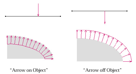
<Placement of force symbol>
> Limiting the size of force symbol
The size of the arrow representing a force is determined to be approximately
proportional to the magnitude of the force. When there are big differences in
the magnitudes of the forces, some of arrows become too large to be appropriately
drawn on the screen. For such circumstances, it is necessary to limit the size
of a r rows. This can be done by selecting "Limit Arrow
Size" item from ![]() menu.
menu.
> Resetting the size of force symbol
As you continue assigning load conditions, the size of arrow may become inappropriate,
even though the load drawing scale can be adjusted using the slide bar of "Load
Condition" dialog. In such case, it is desirable to reset the default size
of the arrow by selecting "Reset Arrow Size" item
from ![]() menu.
menu.
|
|
|
|