![]()
| Postprocessing of Continuum Analysis > Visualization of Seepage Analysis Data > Visualization of flow discharge |
|
|
|
|
||
Visualization of flow discharge
The flow discharge through a designated section can be viewed interactively. The section can be set at arbitrary position and in arbitrary direction as desired. There are some differences between 2-D and 3-D seepage models in setting the section.
> Getting flow discharge in a 2-D seepage model
The flow section is represented by a straight line in 2-D seepage model. The cross section is interactively set and the discharge through this section is viewed by the following procedure:
|
1) Select "Discharge" item from "Seepage" submenu
of |
||
|
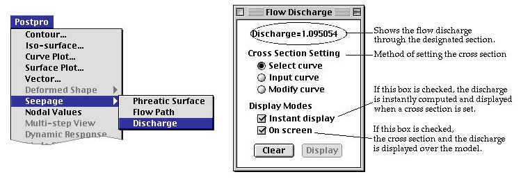
"Flow Discharge" dialog opens. The flow section is interactively designated with the aid this dialog, and the discharge is displayed in the section. |
||
 |
||
|
2) Choose the methods of setting the cross section in "Flow Discharge" dialog. |
||
|
- "Select curve" : The flow section is designate by selecting an existing straight line. This line may or may not be part of the analysis model. |
||
|
- "Input curve" : The flow section is designate by creating a new straight line. |
||
|
- "Modify curve" : The flow section is continuously updated by modifying an existing straight line. |
||
|
3) Choose the display mode. |
||
|
- "Instant display" : If this box is checked, the discharge is instantly computer, and displayed as soon as the cross section is designated. |
||
|
- "In screen" : If this option is on, the discharge is displayed over the cross section image on the main window. |
||
|
4) Set the cross section by the method chosen in step 2). |
||
|
If "Instant display" mode is on, the discharge is displayed instantly as soon as the section is set. The discharge is displayed on "Flow Discharge" dialog. If "On screen" mode is on, the display and its direction is indicated over the cross section drawing. |
||
|
5) Click |
||
|
If "Instant display" mode is on, this step is not necessary. button is enabled only when "Instant display" mode is on. |
||
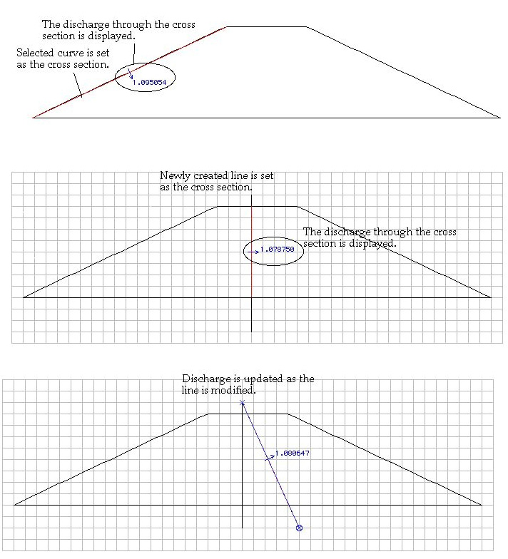
< Displaying the discharge through specified cross section >
> Getting flow discharges through multiple cross sections
More than one cross section can be specified for computation of discharge at
the same time, simply by setting the cross sections one after another. Setting
new cross section does not replace the old setting. Click ![]() button
to clear the setting.
button
to clear the setting.
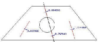
< Setting multiple cross sections for display of discharge >
> Getting flow discharge in a 3-D seepage model
The flow section is represented by a plane or a surface mesh in 3-D seepage model. The cross section is interactively set and the discharge through this section is viewed by the following procedure:
|
1) Select "Discharge" item from "Seepage" submenu
of |
||
|
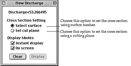
"Flow Discharge" dialog opens. The items of the dialog are not the same as that of 2-D model. |
||
 |
||
|
2) Choose the methods of setting the cross section in "Flow Discharge" dialog. |
||
|
- "Select surface" : The flow section is designate by selecting an existing surface mesh. The surface mesh should be part of the analysis model. |
||
|
- "Set cut plane" : The cross section is defined by the cut plane which is usually used for contouring. |
||
|
3) Choose the display mode. |
||
|
It is the same as 2-D model. "Instant display" option is disabled if the method of setting cross section is "Set Cut Plane". |
||
|
4) Set the cross section by selecting surface meshes if "Select surface" option is chosen in step 2). |
||
|
It is possible to specify more than one surface mesh as the cross sections. The discharge is displayed over each of the surface meshes if "On screen" display mode is on. The sum of the discharge is also displayed on "Flow Discharge" dialog. |
||
|
<Setting cross section by selecting surface meshes> |
||
|
5) Set the cross section by cut plane if "Set cut plane" option is chosen in step 2). |
||
|
If this option is chosen, the cut plane setting mode is automatically
activated, and "Instant display" mode is turned off. Instead,
|
||
|
6) Click |
||
|
If "Instant display" mode is on, this step is not necessary.
|
||
|
7) Click |
||
|
The setting of the cross sections is cleared by clicking |
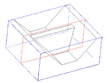
<Setting the cross section by cut plane>
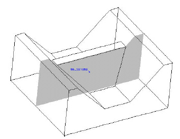
<Getting the discharge through the cross section>
|
|
|
|