![]()
| Diagrams for Frame Analysis > Diagram Related Function > Manipulating the diagrams |
|
|
|
|
||
Manipulating the diagrams
There are functions to control the display of diagrams, such as adjusting the scale of the diagram, changing the direction of the diagram, updating the diagram and so on. Some of them are provided as menu commands which are shown in the second part of the menu. Some of these functions are not provided as menu commands.
> Displaying more than one diagram
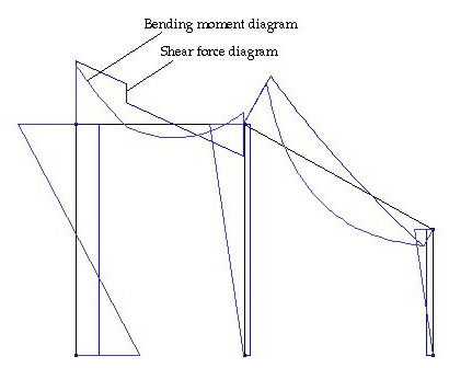
More than one diagrams can be displayed at the same time by choosing the display items with shift key pressed. As an example, the shear force diagram and the bending moment diagram are displayed together in the figure below. To get such an image, first choose "Shear Force" command from menu. Now that the shear force diagram is displayed on the main window, press Shift key and choose "Bending Moment" command. Then, the bending moment diagram is overlaid on top of the shear force diagram. In this example, all the texts are turned off by pressing Control key in order to relieve complexity of the display.
It is also possible to remove a diagram from overlaid diagrams. Choose the menu command corresponding diagram to remove. Then, the display is updated with removal of the chosen item.
On the other hand, if a new diagram command is chosen from menu without pressing shift key, all the currently displayed diagram are replaced by the newly selected item. All the menu items corresponding to the currently displayed diagrams are checked in front.

< Shear force diagram overlaid with bending moment diagram >
> Clearing diagram
To remove the diagram(s), choose "Clear Diagram"
command from ![]() menu.
All the diagrams are cleared, and only the structural members are displayed.
The check marks in front of the currently displayed items are also cleared.
menu.
All the diagrams are cleared, and only the structural members are displayed.
The check marks in front of the currently displayed items are also cleared.
> Redrawing diagram
To update the diagram after changing the model, choose "Redraw
Diagram" command from ![]() menu.
The diagrams are redrawn with the new analysis results.
menu.
The diagrams are redrawn with the new analysis results.
If instant drawing mode is turned on, the diagrams are automatically updated upon any change in the model data, and therefore, this command has no additional effects. Instant drawing mode is explained in the later part of this section.
> Reversing diagram directions as a whole
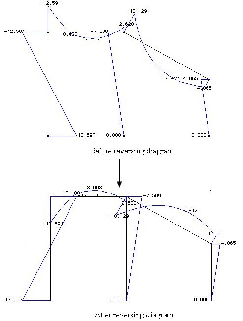
It is sometimes desired to reverse the positive direction of the diagrams. To reverse the diagram direction, choose "Reverse Diagram" command. The values remain unchanged, but the diagram directions of all elements are reversed.

< Reversing the diagram directions as a whole >
> Reversing diagram directions of selected element(s)
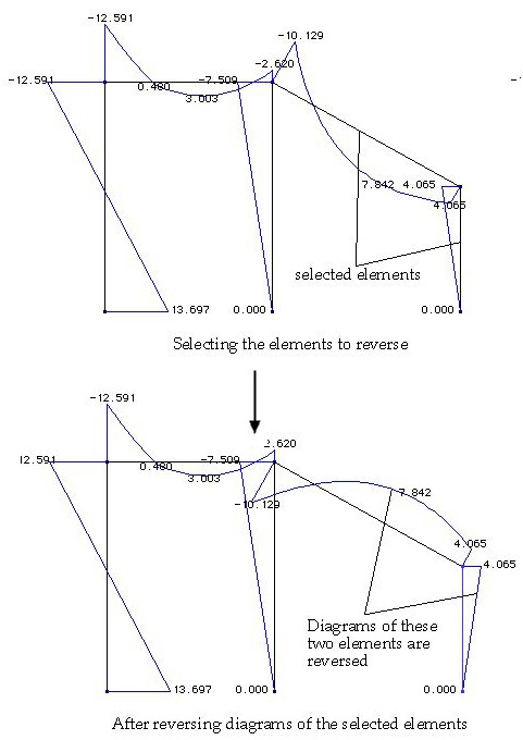
There are circumstances under which the diagrams of only certain elements need be reversed. Selected reversal of the diagram directions can be achieved by the following steps:
|
1) Start the element selection tool |
|
|
Either element selection tool or curve selection tool may be used to select frame elements for diagram reversal. |
|
|
2) Select elements if |
|
|
If a curve is selected, the frame element(s) on the curve is(are) automatically included for diagram reversal. |
|
|
The diagram(s) of selected element(s) is(are) reversed, but the values remain unchanged. |

< Reversing the diagram directions of selected elements >
> Adjusting the scale of diagrams
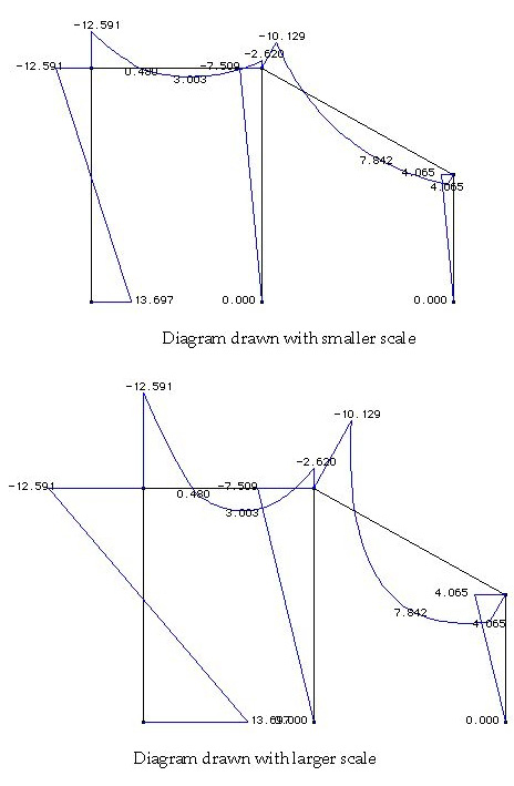
The scale of a diagram is initially determined by VisualFEA, and the diagram of the entire structure is drawn in this scale. The scale can be altered interactively using the scale slider as shown below.

To bring up the slider, choose "Adjust Diagram Scale" command from menu. The scale of the diagram may be enlarged or reduced by moving the nob of the slider. Diagrams with different scales are compared in the following example.

< Adjusting the scale of the diagrams >
|
|
|
|