Studying Stiffness Equation Assembly and Solution
|
Studying Stiffness Equation Assembly and Solution |
|
|
| |
||
Displaying the stiffness matrix in frontal form
The frontal solution procedure is the most widely used method of assembling and solving the finite element equations. This method is distinguished from other solution methods in that some d.o.f. are eliminated while only the necessary parts of the equations are assembled. The eliminated d.o.f. are stored in secondary memory, and retrieved later for back substitution. Thus, only a small number of d.o.f. reside in the primary memory at a given stage. They are called active d.o.f. If all the columns of an active d.o.f. are assembled completely, the d.o.f. is eliminated. The empty space vacated by the eliminated d.o.f. is filled by new active d.o.f. introduced by assembly of another element stiffness matrix. In order to start displaying the stiffness matrix in frontal form, choose ¡°Frontal Solver¡± item from the popup menu of ¡°Stiffness Assembly¡± dialog.
The assembly and elimination process of frontal method is displayed in two parts as shown in the figure below. The left part represents the primary memory space in which the equations of active d.o.f are stored, and the right part the secondary memory space, in which the equations of the eliminated d.o.f. are stored.
< Frontal solution procedure >
Frontal length
The frontal length is the number of active d.o.f. at a certain solution stage. This f rontal length changes, and is displayed with label ¡°Front L¡± at the top of the window, while the solution process is going on. The maximum length through the whole solution process is called maximum frontal length, and is also displayed with label ¡°Max. Front L.¡± The primary memory space should be sufficient to accommodate the maximum frontal length. The maximum frontal length affects the solution time as well.
Examining the effect of element number optimization
The maximum frontal length is the most important factor determining the required
memory and the computing time for the frontal solution process, and is significantly
affected by the element numbering, instead of node numbering for band width.
Therefore, in order to improve the computational efficiency, element numbering
should be optimized prior to solving the system equations by the frontal solution
method. The effect of the element number optimization can be identified by noticing
the reduced maximum frontal length. Choose ¡°Optimize Element No.¡± item from
![]() menu. Then, the element number optimization is processed, and the maximum frontal
lengths before and after optimization are displayed. At the same time, the frontal
solution space is updated in accordance with the new element numbering.
menu. Then, the element number optimization is processed, and the maximum frontal
lengths before and after optimization are displayed. At the same time, the frontal
solution space is updated in accordance with the new element numbering.
Animating the frontal solution process
The process of frontal solution can be graphically visualized by animation.
Click ¡°Play¡± button to
start animation. At the beginning of the animation, all the equations are cleared
from both the primary and the secondary memory spaces.
The animation displays the frontal solution process. While animation is going on, the following should be noticed on the mesh drawn in the main window:
| The assembled elements are marked in blue. | |
| The most recently assembled element is marked in red. | |
| The node being eliminated is marked by a small circle. |
At the same time, the following should be noticed in the primary and secondary memory spaces.
|
Equations of the active d.o.f. are displayed in the primary memory space. |
|
|
Equations of eliminated d.o.f. are displayed in the secondary memory space. |
|
|
The d.o.f. associated with the most recently assembled element are marked in red. |
|
|
The d.o.f. under elimination is marked in blue. |
|
|
The frontal length is shown at top of the window. The maximum of the frontal length reached so far is repeatedly updated. |
The animation also illustrates the movement of eliminated equations from the primary memory space to the secondary memory space.
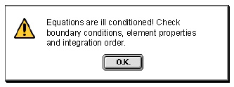
For successful animation, the model should be assigned properly with element properties and boundary conditions. Otherwise, the animation will be aborted in the middle with the following message.

The animation can also be interrupted by the user by clicking ¡°Stop¡± button
, and resumed by clicking ¡°Play¡± button
.
3-3-4
Examining the frontal solution process step by step
The frontal solution process can be examined more closely by proceeding step
by step. This step by step display of the process may be started from scratch,
or in the middle of animation. In order to move the process one step forward,
click ¡°Forward¡± button .
Progress of solution process can be visualized by repeating the button click
continuously. In order to move the display one step backward, click ¡°Backward¡±
button
.
While step by step display is going on, the mesh on the main window and the equations in the primary and the secondary memory are illustrated in the same way as in case of animation.
< Frontal solution procedure >
|
|
|
|