![]()
![]()
![]()
![]()
| Basic User Interface > Viewing Control > Rotating view |
|
|
|
|
||
Rotating view
Rotating view can be interpreted in two different concepts:
|
The user's view direction is fixed, and the 3-dimensional space containing the finite element model is rotating with respect to the view direction. |
|
| The 3-dimensional space is fixed, and the user's view direction is changing. In either case, the actual data are not affected, but only the display on the screen is changing. There are a few methods of rotating view in one of the two concepts. |
It is also possible to rotate the actual coordinates of the finite element models. But it is termed here as "model rotation" and has nothing to do with view rotation. Model rotation is explained in Chapter 4.
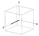
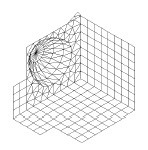
> Rotating view using virtual track ball
The virtual track ball is shown in the tool palette, and can be manipulated using mouse with similar feel of a real track ball in the following ways:
|
1) Place the screen cursor over the virtual track ball. |
|
|
Place the cursor at a point of the virtual track ball as if you were placing your finger tip on the actual track ball. |
|
|
2) Press the mouse button. |
|
|
The current rotation angle about each coordinates axis is displayed at the bottom of the tool palette. |
|
|
3) Move the mouse with button pressed. |
|
|
While you are moving the mouse, the virtual track ball is rotating in accordance with the cursor movement, in the same way as a real track ball rotates along with your finger tip. The rotation angles displayed at the bottom of the tool palette are constantly updated in accordance with the track ball rotation. |
|
|
4) Release the mouse button. |
|
|
Rotation of the virtual track ball ends, and the view rotation is conformed to the track ball rotation. |
Any action in progress is not interrupted by operation of virtual track ball. For example, if you entered part of control points of a spline curve before rotating view, you can complete the curve by entering the remaining control points after the rotation.
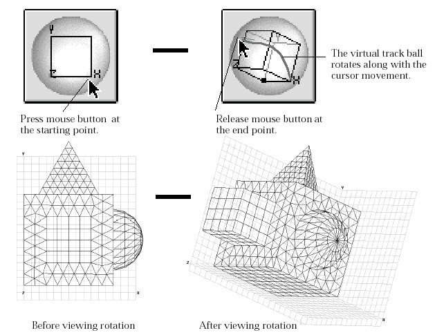
<Rotating view using virtual track ball>
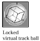
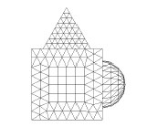
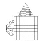
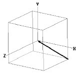
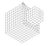
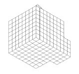
> Rotating view using bounding box
The viewing rotation can also be manipulated directly on the main window using a so-called bounding box, which is a rectangular parallelepiped enclosing the modeling objects. This method is useful for more precise rotation, but interrupts other action in progress.
 |
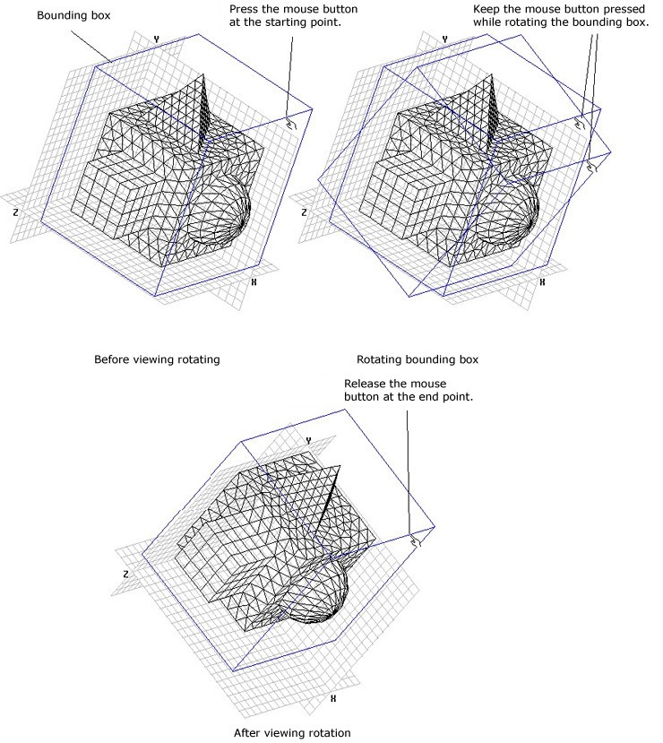
1) Lock the virtual track ball by clicking it with key |
|
The locked virtual track ball is displayed as a pressed button as shown left. At the moment the virtual track ball is locked, the bounding box appears on the screen. |
|
|
2) Move the screen cursor over an edge of the bounding box. |
|
| The shape of the cursor changes into , when the cursor is placed within the main window. | |
|
3) Press the mouse button, and drag the edge of the bounding box. |
|
| As you drag the edge, the bounding box rotates along with the edge. | |
|
4) Release the mouse button. |
|
|
Rotation of the bounding box ends, and the view rotation is conformed to the track ball rotation.Accordingly, the string of rotation angles and the virtual track ball are updated. |
The virtual track ball is still effective in locked state. In order to unlock
the virtual track ball, click the track ball once again with![]() key (Windows :
key (Windows :![]() key) pressed, or start any other tool.
key) pressed, or start any other tool.
< Rotating view using bounding box >
> Rotating view using key board
 |
While the view is being rotated, the angles of rotation about
X, Y and Z axes are displayed at the bottom of the tool palette as shown
left. Viewing rotation can be achieved by directly editing the text of these
rotation angles. Click one of the text boxes, and edit the text. After all
the angles are set to the desired values, press |
> Getting the preset viewing rotations
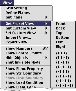 |
A number of typical views, such as front view, top view, etc., are p
reset for quick retrieval. The desired viewing rotation is obtained simply
by selecting one of the preset view items from The rotation by each of the preset view is indicated on the following table. The submenu items include 8 oblique rotations in the form of (l,m,n), in which l, m and n implies the view directions respectively in X, Y and Z axis. |
< Preset view rotation items >
|
Menu Item
|
View Direction
|
Rotated View
|
Menu Item
|
View Direction
|
Rotated View
|
|
Front
|
 |
 |
Back
|
 |
 |
|
Top
|
 |
 |
Bottom
|
 |
 |
|
Left
|
 |
 |
Right
|
 |
 |
|
( 1, 1,1)
|
 |
 |
( 1, 1,-1)
|
 |
 |
|
( 1, -1, 1)
|
 |
 |
(1, -1,-1)
|
 |
 |
|
(-1, 1, 1)
|
 |
 |
(-1, 1,-1)
|
 |
 |
|
(-1, -1, 1)
|
 |
 |
(-1, -1,-1)
|
 |
 |
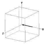
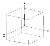
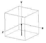
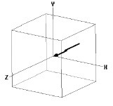
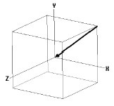
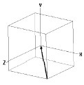
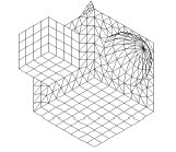
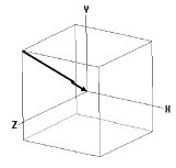
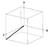
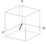
> Setting view direction
Rotation of the view can be specified by the view direction, which is directed from user's eye to the screen. You can set the view line, and get the viewing rotation by forcing the line to be the view direction.
|
1) Lock the virtual track ball by clicking it with contr l key pressed, if it is not locked. |
|
|
If you click the virtual track ball with c o n t rol key pressed, the shape of the track ball becomes a pressed button with an arrow as shown to the left. This indicates that you are in the "view direction" mode. At the moment the virtual track ball is locked, modeling objects appears to be surrounded by a bounding box with cross hairs re p resenting the current view point and direction. |
|
|
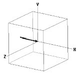
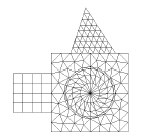
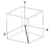
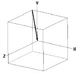
2) Specify the new view point by clicking a point on one of the faces of the bounding box . |
|
| The new view point is marked by cross hairs, and the view line is represented by a straight line connecting the point and the center of the bounding box. | |
| If you want to specify the new view point on one of the back
faces, click with key |
|
|
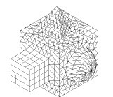
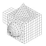
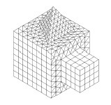
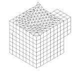
3) Double click the mouse button. |
|
|
Double clicking rotate the view so that the specified view line is directed normal to the screen. |

< Setting the view direction >
|
|
|
|