![]()
![]()
![]()
![]()
| Basic User Interface > Model Rendering > Setting rendering style |
|
|
|
|
||
Setting rendering style
For graphical re p resentation of model, VisualFEA provides diff e rent styles of rendering as follows.
| wireframe mesh without hidden line removal | |
| wireframe mesh with hidden line removal | |
| outline | |
| shading | |
| transparency shading | |
| broken mesh |
The default style is wireframe mesh. Choose corresponding item from ![]() menu
to change the rendering style. The screen image of the model is immediately
updated using the new style. The style remains effective for future model rendering
until you change the style again.
menu
to change the rendering style. The screen image of the model is immediately
updated using the new style. The style remains effective for future model rendering
until you change the style again.
> Rendering by wireframe with or without hidden line removal
Wireframe rendering is the one represented by the mesh lines of the model. For solid models, the mesh lines inside the volume are not shown, and only lines on outer surface meshes are drawn. It is efficient and convenient in many cases to apply wireframe rendering owing to its speed. However, the shape of shell or 3-D solid may sometimes look obscured when re n d e red by wireframe mesh without hidden line removal. The visual clarity is much improved by removing the hidden lines. But, rendering with hidden line removal usually takes much longer time than the one without.
> Rendering by outline
Rendering by outline further simplifies the model image. Only the outlines necessary for proper re p resentation of the model are extracted and used in rendering. Its rendering speed is almost equivalent to that of wireframe mesh with hidden line removal. This style of rendering is also useful for rendering of the outer surface with contours inside the volume.
> Rendering by shading or transparency shading
Rendering by shading produces more realistic view of the model. The model is represented by solid surfaces with brightness due to assumed light sources. The directions and intensity of light sources can be adjusted by using "Preference" dialog.
Transparency shading represents the model as a transparent object. This rendering style is also useful for representing the data distribution using iso-surfaces, parallel planes and so on.
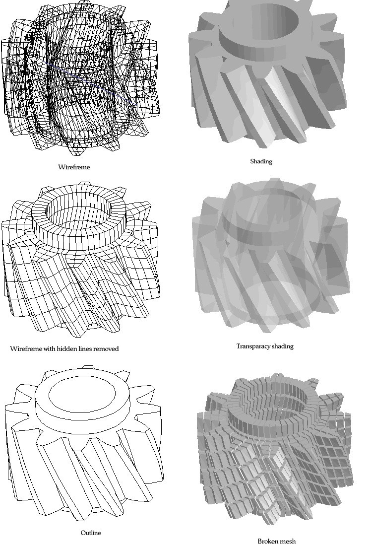
<Styles of model rendering >
> Rendering by broken mesh
Rendering by broken mesh produces image of the model with all the elements
torn apart. In order to get broken mesh image, select "Broken Mesh"
item from ![]() menu.
Then, the following "Broken Mesh Setting" dialog pops up on the screen.
menu.
Then, the following "Broken Mesh Setting" dialog pops up on the screen.
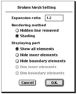
The dialog has following items:
| expansion ratio : Set the value in the editable text box. The expansion ratio determines how the broken mesh expands or shrinks. If this ratio is greater than 1, the broken mesh is obtained by inserting gaps between elements. If it is less than 1, the broken mesh is obtained by shrinking the individual elements in their original places and thus creating gaps between elements. | |
|
rendering method : Broken meshes can be rendered either by shading or by wireframe mesh with hidden line removed. Click appropriate dialog button to select the option. |
|
|
rendering part : This item determines which part of the model is to be shown using broken mesh. |
|
|
- "Show all elements" : All elements are included in the broken mesh. |
|
|
- "Hide inner elements" : Only the elements on the outer surface will be drawn. |
|
|
- "Hide boundary elements" : Only the inner elements will be drawn. |
After setting all the above items in the dialog, and click "O.K" button. Then, the broken mesh image is drawn.
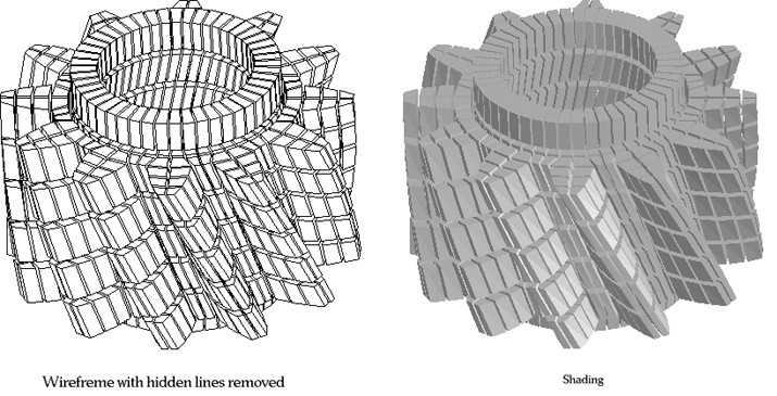
<Rendering styles of broken mesh>
|
|
|
|