![]()
![]()
![]()
![]()
| Curves and Surface Primitives > Creating Curves and Surface Primitives > Creating parametric surfaces |
|
|
|
|
||
Creating parametric surfaces
 |
Press the surface tool button |
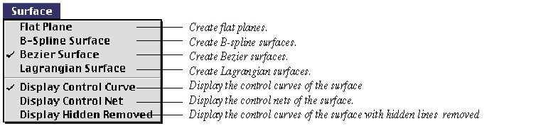
> Flat Plane
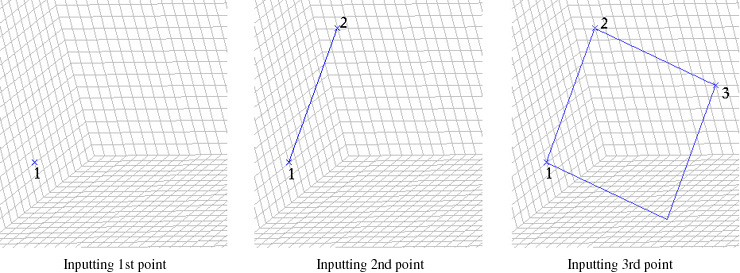
While this type is marked, a flat plane is created by entering 3 points. As exemplified in the following figure, the flat plate is re p resented by a diamond shape. The first and the second input point form an edge of the diamond, and the second and the third point form another one.
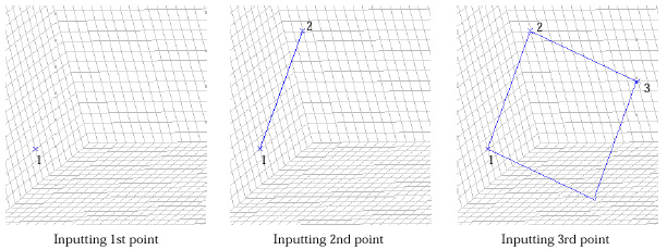
< Creating a flat plane >
Modification mode is automatically activated right after a flat plane is created.
Any of the three points can be selected and modified without sequence. Place
the screen cursor on one of the points marked with ![]() ,
and press the mouse button. Then, the mark will be changed into
,
and press the mouse button. Then, the mark will be changed into ![]() .
Keep the mouse button pressed while moving the cursor to the desired point.
The
.
Keep the mouse button pressed while moving the cursor to the desired point.
The ![]() mark
moves along with the cursor. Release the mouse button. Then, the selected point
moves to the last point of
mark
moves along with the cursor. Release the mouse button. Then, the selected point
moves to the last point of ![]() mark.
The new coordinates of the selected point can also be entered directly using
the keyboard. When one of the three points is selected and marked by
mark.
The new coordinates of the selected point can also be entered directly using
the keyboard. When one of the three points is selected and marked by ![]() .
the coordinates of the point are displayed in the editable text boxes at the
bottom of the tool palette. Edit the coordinate values and press
.
the coordinates of the point are displayed in the editable text boxes at the
bottom of the tool palette. Edit the coordinate values and press![]() key
(Windows :
key
(Windows : ![]() key)..
Then, the point moves to a new location corresponding to the entere d coordinates.
key)..
Then, the point moves to a new location corresponding to the entere d coordinates.
> B-spline Surface
While this type is . marked, a B-spline surface is created by specifying the size of the control net, entering 3 corner points and consecutively editing the coordinates of the control points. The size of the control net is defined in the form of m n and e n t e red using "Surface" dialog. Here, the control net is a lattice of (m+ 1 ) (n+ 1 ) control points in array of (m+1) rows and (n+1) columns.
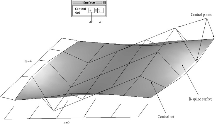
< Control net defining a surface >
To create a B-spline surface,
| 1. Enter m x n, the size of the control net in the "Surface" dialog. | |
| 2. Input the first and the second point. | |
| They form a line connecting two corners of the control net. The line is also an edge of the control net, consisting of (m+1) control points.rectangle. | |
| 3. Input the the third point. | |
| The initial state of the control net is constructed by entering the third point. Another edge of the control net is aligned with the second and the third point. But, the corner of the control net may or may not coincide with the third point. The actual coordinates of the corner point are determined so that the control net forms a rectangle |
All the control points on the control net lies initially on a plane. In order to construct a desired surface, the control points should be moved, one by one, to the desired positions as follows.
|
1. Select the control point to move, by clicking the point. |
|
|
The selected control point is highlighted by mark. |
|
|
2. Move the selected control point. |
|
|
The control point can be moved either by dragging the point on the screen, or by entering the new coordinates in the text boxes of the tool palette. |
|
|
3. Repeat the step 2, and 3 for all the control points which should be modified. |
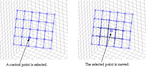
< Modifying the control net >
> Bezier Surface
When these options are effective, Bezier surfaces and Lagrangian surfaces are respectively created by constructing and consecutively editing the control net of the surface in the same manner as that of B-spline surface.
|
|
|
|