![]()
![]()
![]()
![]()
| Mesh Generation > Frame Element Generation > Creating frame elements using straight lines or curves |
|
|
|
|
||
Creating frame elements using straight lines or curves
A frame members which may be modeled by a straight line or by a curve. One frame member may consist of one element or multiple elements. A frame element is automatically generated on a straight line, but elements are not assigned on a curved members, until it is divided. A curved member may be approximated by multiple line elements. Even a straight member sometimes needs to be modeled by more than one element in connection with load assignment, force diagrams and so on as exemplified in the following figure.
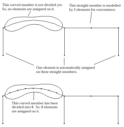
< Example of element generation on frame members >
> Creating a frame element by inputting a straight line
If the analysis subject is defined as a frame, i.e, 2-D truss, 3-D truss, 2-D frame or 3- D frame, in the problem setup, a frame element is automatically assigned on a newly created straight line. Line elements are usually assigned on a line or a curve by dividing it. So, assigning an element on a line is equivalent to dividing it into one. Dividing a curve into one implies creating a two node on both ends of the selected curves and can be achieved by the menu command "Divide into 1." But, you don't have to use this command, because it is automatically done when a straight line is newly created. Automatic element assignment facilitates modeling frame, because most frame members are straight line. This automatic assignment is applied only for a frame.
> Generating frame elements by dividing curves
As mentioned previously, a straight line is the only frame element shape available in VisualFEA. Therefore, a curved member should be modeled by multiple pieces of line segments which can be obtained by dividing curves. When a curve is created, initially no elements are assigned on it . Elements are generated on the curves when they are divided. The curves may be divided into as many elements as necessary. More elements will produce better approximation of the curved members, but will increase the complexity of the model as exemplified below.
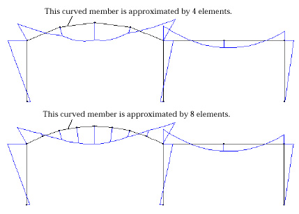
< Bending moment diagrams with different approximation of curved member >
Straight lines are initially assigned with an element, but more than one elements may be generated on it if necessary. Division of a straight line does not affect the analysis results, because straight members can be modeled exactly by one element. However, there are situations under which straight members need be modeled by multiple elements. In such cases, you may create either multiple line segments with one element or a straight line with multiple elements. The following figure shows an example of such a case in which distributed load is applied on some part of a straight member. The inclined straight line member is divided to three parts, because distributed load cannot be applied partially on an element in VisualFEA.
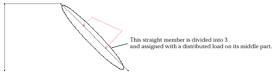
< Example of a straight member partially loaded with trapezoidal force >
|
|
|
|