![]()
![]()
![]()
![]()
| Mesh Generation > Frame Element Generation > Creating frame elements using mesh generation functions |
|
|
|
|
||
Creating frame elements using mesh generation functions
L a rge and complex skeletal structures like buildings consist of large number of frame members. In modeling such a frame structures, it is difficult to create individual members one by one. Such a model can be constructed simply by generating frame elements as a mesh and then editing part of the mesh if necessary. Having identified the structure as a frame, mesh lines are recognized as frame elements. Frame elements can be generated using the following mesh generation functions:
| "2 Edges" | |
| "3 Edges" | |
| "4 Edges" | |
| "Extrude (Surface)" | |
| "Extrude to Curve" | |
| "Sweep (Surface)" | |
| "Revolve (Surface)" | |
| "Twist (Surface)" |
In fact, the above list includes all techniques of surface mesh generation except "Auto Mesh" and "Auto Mesh On Primitive." These two functions are excluded, because they cannot control the shape of the generated mesh as normally required in modeling frames. Meshes with either triangular or quadrilateral cells (basic formation of frame members corresponding to an element in a surface mesh) may be generated. The arrangement of triangular cells can be controlled by the options "Left", "Right" and "Union Jack" provided as radio buttons in the dialog boxes for mesh generation. The usage of the setting is the same as is in surface mesh generation. The "Optimal" button is disabled, because regular shape of the mesh is not guaranteed by this option.
The following example shows how efficiently a complex frame model can be constructed by using mesh generation functions. First, a frame mesh is generated using "2 Edges" and then redundant members are deleted. Lastly, some members are added.
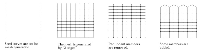
< Example of constructing frame model using mesh generation >
|
|
|
|