![]()
| Data Assignment > Sequentially Staged Modeling > Concept of sequentially staged modeling |
|
|
|
|
||
Concept of sequentially staged modeling
Stage is a core concept of the sequentially staged modeling. This section describes the finite element procedures based on the stages, and the inter-relation of analysis results and modeling data between stages.
> The base model and the stage models
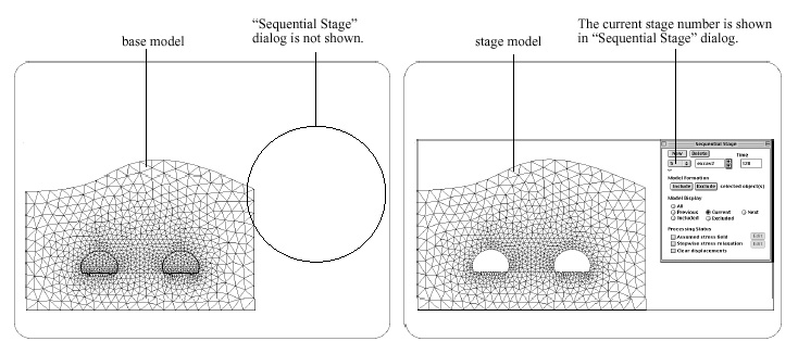
A sequentially staged model consists of 2 or more stages. Each stage has all ingredients of finite element analysis by itself and is modeled to re p resent the actual situation with changing geometry, properties, and load conditions. The finite element analysis model for a stage is termed here as "stage model", while the model with all data shared by all stages are termed as "base model." A sequentially stage modeling always involves one base model and 2 or more stage models. The base model is displayed on the screen when the "Sequential Stage" dialog is not shown. The stage model of the current stage is displayed when "Sequential Stage" dialog is opened. You can move to the desired stage either by using the stage number popup menu(Windows: dropdown list), or by using the scroll buttons. The current stage number appears as the popup text. The current stage can also be identified by the label displayed in the label text box. The geometry, properties, boundary conditions and load conditions of the current stage model is displayed in the main window if the dialog is opened and the display mode is set to "Current". At the moment you close the dialog, the display on the main window returns to the base model.

<Base model and stage model>
> Data sharing and inheriting
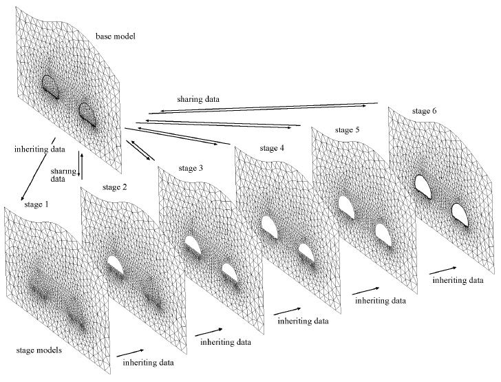
All the stage models share the data of the base model. In other words, the base model comprises all the data included in the stage models. The first created stage model (the stage model of stage 1) initially inherits its data from the base model, and is later modified to keep only necessary data by using exclusion, assignment or clearing actions. Likewise, a subsequent stage model initially inherits its data from the preceding stage model, and is modified later by various actions. Creation or modification of geometric objects, i.e., curves and meshes are allowed only for the base model. Thus, new objects cannot be attached to a stage model directly. The geometric objects created for the base model are automatically inherited to all the currently existing stages. On the other hand, properties and load conditions can be assigned directly to a stage model. Any assignment performed at a stage level is applied to the corresponding stage model, and also included in the base model. But the assignment is not applied to the other stage models. Nevertheless, any assignment to the base model is automatically inherited to all the currently existing stages.

<Concept of data sharing and inheriting>
> Solution process of stage models
A complete processing of finite element solver is performed for each of the stage model. The processes are repeated, starting from the first stage and proceeding sequentially to the last. Each process of a stage model is not independent from the others. A stage model is processed in association with its preceding or subsequent stage. The solution results of a stage model are reflected in the processing of the next stage model. For example, unbalanced forces resulting from excavation at a stage are relaxed over the next few stages with prescribed rates. The solution results such as displacements, stresses and so on are accumulated stage after stage. The data accumulation can be artificially controlled if necessary. As an example, the nodal displacements are cleared at the first stage while the computed stresses a re retained, which is usually applied to modeling construction stages in consolidated soil.
> Procedure of sequentially staged modeling
A stage model is constructed in the form of extracting necessary components from the base model. The procedure of sequentially staged modeling can be summarized as follows:
|
1) Create the base model. |
|
|
It is recommended to complete creating the base model before creating the stages, although the base model may be added or modified in the middle of working with stage models. |
|
|
2) Create stage models and build the geometry of the stage models. |
|
|
The geometry of a stage is constructed initially by inheriting the geometry f rom the base model or from the previous stage, and then modified by "Include" and "Exclude" actions. |
|
|
3) Build the data assignment of each stage model. |
|
|
P roperty and load condition data of a stage is constructed initially by inheriting the data from the base model or from the previous stage, and then modified by assigning or clearing data. |
|
|
4) Execute the solution process. |
|
|
The finite element solution process is launched in the same way as non-staged
models. Select "Solve" item of |
|
|
5) Postprocess the analysis results. |
|
|
The analysis results of the staged model are arranged and saved as a sequential process. The visualization of the analysis results can also be controlled sequentially in accordance with the staged progress. |
|
|
|
|