![]()
| Data Assignment > Structural Element Properties > Defining element properties of truss and frame elements |
|
|
|
|
||
Defining element properties of truss and frame elements
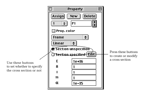
Frame and truss elements are line segments with specific cross sections. The property set of such elements includes the data related to the cross section such as section area, area moment of inertia, and so on. These data can be defined either directly inserting the values to the corresponding items, or indirectly by specifying the shape and the dimensions of cross section. " Property" dialog for frame or truss element is diff e rent from dialogs for other analysis class elements as shown below.
There are 2 radio buttons to set whether to define the element properties with or without defining the cross section. Turn on "Section unspecified" radio button to define the element property without specifying the cross section. Otherwise, turn on "Section specified" radio button to specify the cross section as explained in the following section.

> Defining cross sections of a truss or a frame member
The cross sectional properties of a structural member can be inputted by dimensioning the section of a selected shape in the following order.
|
1) Click "Defined section" radio button or |
||
| Then, "Section Properties" dialog appears on the screen. | ||
|
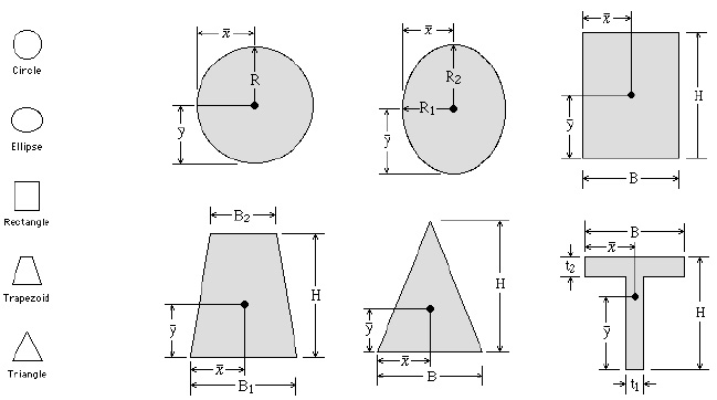
<List view icons and dimensional notations of cross sections> |
||
| 2) Scroll the list view of section icons so that the desired icon may be seen. | ||
| The current version of VisualFEA has 13 shapes of defined cross section. The list view on the left of the dialog contains the icons of section shape. Only 4 of them are shown. The desired one can be made visible by using the scroll bar of the list view. | ||
|
3) Select the desired shape of cross section. |
||
|
Click the icon of the desired shape. Then, there appears the detailed view of the selected cross section with dimensional notations, and editable text boxes for inputting the dimensions. |
||
|
4) Input dimensions of the section. |
||
|
Insert the texts into the editable text items representing the dimensions of the cross sections. If all the dimensions are supplied, the computed sectional properties are displayed at the right bottom portion of the dialog. |
||
|
5) Set the orientation of the section if necessary. |
||
|
If the desired orientation of the section is not the same as the one displayed on the dialog, that can be altered by choosing one of the following radio buttons: |
||
|
- "Original" : The orientation is maintained as it is. |
||
|
- "Flip vertical": The section is flipped about a horizontal axis. |
||
|
- "Flip horizontal": The section is flipped about a vertical axis. |
||
|
- "Rotate right": The section is rotated 90 clockwise. |
||
|
- "Rotate left": The section is rotated 90 counter clockwise. |
||
|
- "Rotate 180 ": The section is rotated 180 . |
||
|
6) Click |
||
|
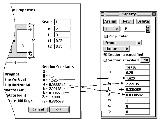
The computed cross sectional properties are automatically inserted into the corresponding items of "Property"dialog. |
||


< List view icons and dimensional notations of cross sections >

< Automatic insertion of computed cross sectional properties>
Once the cross sectional properties are automatically inserted into the appropriate
text items of "Property" dialog, the cross section data is linked
to the property set. Thus, "Defined section" radio button is turned
on for this set. The cross section of this property set can be edited later
by clicking ![]() button
and modifying the text items of "Section Properties" dialog. However,
if any item automatically inserted from the cross sectional definition is manually
modified, the link between the property set and the section properties is broken
and cannot be recovered . Thus, "Undefined section" radio button is
turned on for this property set.
button
and modifying the text items of "Section Properties" dialog. However,
if any item automatically inserted from the cross sectional definition is manually
modified, the link between the property set and the section properties is broken
and cannot be recovered . Thus, "Undefined section" radio button is
turned on for this property set.
|
|
|
|