![]()
| Data Assignment > Structural Element Properties > Using embedded bars |
|
|
|
|
||
Using embedded bars
Similarly to slip bars, embedded bars are also used in modeling stiffening material embedded within planar or 3-D solid structures. Embedded bars are more convenient and flexible to use than the slip bars, because they can be arbitrarily placed within continuum. Embedded bars cannot be used alone, but may be included in plane stress, plane strain, axisymmetric, or 3-D solid structures.
> Characteristics of embedded bar elements
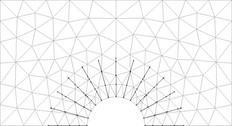
Embedded bars and slip bars are similar in their usage as stiffening line segments embedded within continuum, but diff e rent in their characteristics and in their modeling method. A slip bar is an element which has nodes and its own displacement field, while an embedded bar is not an independent element but a stiffening segment embedded within continuum elements. Thus, an embedded bar has neither independent displacement field nor nodes. Its displacements are defined only through the deformation of the surrounding elements. The stiffness of the embedded bars are directly added to the surrounding elements. The strains of embedded bars are computed from the displacements of the surrounding elements. An embedded bar can pass through a number of elements without restriction in the position or in the direction of its path. Embedded bars may be placed freely within continuum without involving nodal connectivity conditions as shown in the figures of this and the next pages. So, embedded bars can be employed conveniently in modeling complex reinforcement within continuums, especially in combination with unstructured meshes.

< An example of embedded bars placed within a 2-D unstructured mesh >
> Creating embedded bars
Any straight line can be defined as an embedded bar by assignment of element properties as explained below.
|
1) Create straight lines using the line tool |
|
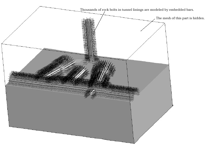
| Many embedded bars with a certain regular arrangement may be created efficiently by using duplication of curves. The figure at the bottom of this page shows an example of thousands of embedded bars created mostly by "Duplicate and Move" and "Duplicate and Revolve". Refer to "Duplicating curves and surface primitives" section of Chapter 3. | |
|
2) Start property assignment procedure. |
|
|
Choose "Element Property" item from |
|
|
3) Choose "Embedded Bar" item from the popup menu in "Property" dialog. |
|
|
The data items in "Property" dialog are altered to the items of embedded bars. |
|
|
4) Enter the value for each data item. |
|
|
The data items are related to the axial stiffness of the embedded bar. It is assumed that the section area of the embedded bar is subtracted from the embedding elements. Let Ae and Ee be the section area and the elasticmodulus of the embedded bar, and Eo be the elastic modulus of the embedding element. Then, the stiffness contribution of the embedding bar is |
|
|
|
|
| 5) Select one or more lines to assign embedded bar properties. | |
|
6) Click |
|
|
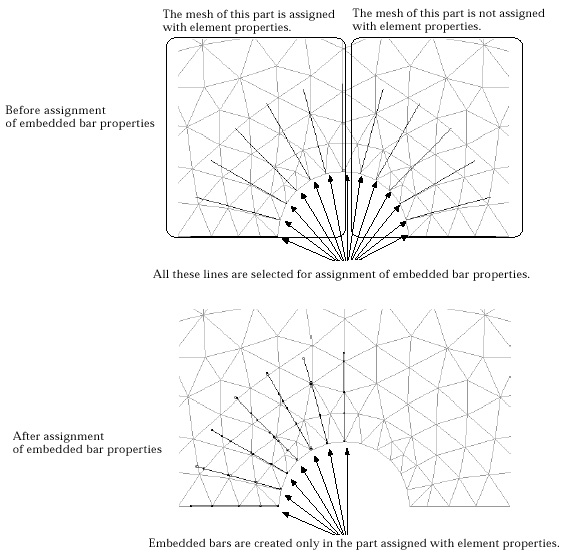
The selected curves turn into embedded bars only when the surrounding continuum elements are assigned with element properties as illustrated by the f i g u re below. The intersections of embedded bars and element edges are marked by small circles. |

< An example of embedded bars in a 3-D solid model >

< Creation of embedded bars>
> Deleting embedded bar
The embedded bar properties are removed by deleting the embedded bar property set, or by clearing the assigned property set. The line segments remain undeleted, although the property assignment is removed.
|
|
|
|