![]()
| Postprocessing of Continuum Analysis > Visualizing Scalar Data by Contours > Setting cross planes for contouring |
|
|
|
|
||
Setting cross planes for contouring
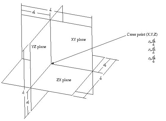
The data distribution around a specific point within a 3-dimensional volume can be visualized effectively using cross planes as auxiliary planes for contouring. Cross planes are also volume visualization aid and consist of 3 orthogonal planes, XY plane, YZ plane and ZX plane, crossing at a specified point, namely the cross point. Once the cross planes are defined, the contour images are drawn on these planes. This method is especially suitable to represent the 3 dimensional variation of data in the vicinity of the cross point. Each of the cross planes can be turned on or off, and the location of the cross point can be specified as described in the following.

< Cross planes and cross point >
> Activating the cross plane setting mode
The cross plane setting mode should be activated in order to start define the cross planes. This can be done by the following steps.
|
1) Start the volume selection tool by pressing |
|
|
One can now select volume object(s) in the model. |
|
|
2) Select object(s) in which the cross planes are to be defined. |
|
|
Select one or more object(s) which form a continuous volume which will contain the cross planes. |
|
|
The cross point is not necessarily within the volume. |
|
|
3) Start the cross plane setting tool by pressing |
|
|
Get into the cross plane setting mode by clicking |

The cross plane setting mode is deactivated simply by activating other tool in the tool palette.
> Setting cross planes
The initial or the previous setting is shown, when the parallel plane setting mode is activated. This setting can be altered interactively as explained below.
|
Turning on or off the cross planes : Each one of the cross planes can
be turned on or off individually by choosing "XY Plane", "XY
Plane" or "ZX Plane" item from |
||
| Setting the mode of representing the location of the cross
point : The positions of the cross planes are determined by that of the
cross point. While the cross plane setting mode is active, the editable
text box labeled "Cross Point" is shown at the lower part of the
tool palette. The text strings display the current location of the cross
point, and can also be used to input the location. The location of the cross
point can be expressed either by XYZ coordinates or by the ratios in X,
Y and Z axis directions. The mode of expressing the location can be selected
by choosing "By Coordinates" or "By Ratio" item in |
||
|
< Editable text item for coordinates of cross point> |
||
| The ratios r x , r y and r z represent the relative location of the cross point with respect to the total length of the model in X, Y and Z directions, and has value between 0 and 1. (Refer to the figure <Cross planes and cross point>) | ||
|
Placing the cross planes by mouse dragging : Each one of the cross planes can be moved to the desired position by mouse dragging by the following steps. |
||
|
1) Select the cross plane to move. |
||
|
Place the screen cursor over the image of the plane, and click the mouse button. The coordinates of the cross point are given in the text box. |
||
|
2) Drag the plane with the mouse button pressed. |
||
|
The selected cross plane moves along with the cursor. |
||
|
3) Release the mouse button. |
||
|
The cross plane settles at the position where the button is released. |
||
|
4) Repeat step 1) 2) and 3) until all the cross planes are positioned as desired. |
||
|
Place all the parallel planes one by one, as explained above. |
||
|
Locating the cross point by keyboard input: The coordinates or the ratios of the cross point can be inputted directly in the text box at the lower part of the tool palette by the following steps: |
||
|
1) Set the appropriate mode of representing the location of the cross point. |
||
|
The mode can be set by choosing "By Coordinates" or "By
Ratio" item in |
||
|
2) Edit the text. |
||
|
Change the location by editing the text of location represented either by coordinates or by ratio. |
||
|
2) Press |
||
|
The edited text of the location is applied by pressing |
> Contouring on cross planes
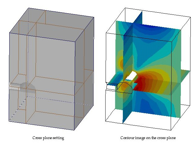
The cross planes are used for contouring data inside 3-dimensional volumes. If cross planes are set immediately prior to opening "Contour" dialog, "Cross Planes" item of the contouring object popup menu is enabled and is selected. (Refer to the previous section, "Setting contouring options".) If the selection of this popup menu item is not altered, the contour will be drawn on the cross planes.
![]()
There are options setting the style of the surrounding boundary surface rendering. Refer to (...) for more detailed description on this subject. Each one of the cross planes can be turned on or off as described earlier this section. A contour image will be drawn only on cross planes which are turned on.

< Setting the cross plane and contouring on the plane >
|
|
|
|