![]()
| Postprocessing of Continuum Analysis > Visualizing Scalar Data by Contours > Setting parallel planes for contouring |
|
|
|
|
||
Setting parallel planes for contouring
The data distribution inside a 3-dimensional volume can be visualized effectively using another volume visualization aid, i.e., parallel planes as auxiliary planes for contouring. Parallel planes are a number of planes defined within selected volumes, normal to the specified coordinate axis. The direction and the location of the planes as well as the number of planes can be set as described below.
> Activating the parallel plane setting mode
The parallel plane setting mode should be activated in order to start defining parallel planes. This can be done by the following steps.
|
1) Start the volume selection tool by pressing button. |
|
|
One can now select volume object(s) in the model. |
|
|
2) Select object(s) in which the parallel planes are to be defined. |
|
|
Select one or more object(s) which form a continuous volume and which will contain the parallel planes. |
|
|
3) Start the parallel plane setting tool by pressing button. |
|
|
Get into the parallel plane setting mode by clicking button in the tool palette. Then, a rectangular box will surround the selected object(s). The initial state of the parallel planes is also shown within the box. At the same time, menu appears on the menu bar as shown below. The parallel plane setting mode is deactivated simply by activating any other tool in the tool palette. |
|
> Setting parallel planes interactively
The initial or the previous setting is shown, when the parallel plane setting mode is activated. This setting can be altered interactively as explained below.
> Setting parallel planes by custom input
There is another method of setting the parallel planes. That is to use "Parallel
Plane Setting" dialog. In order to start the dialog, choose "Custom
Planes..." item in ![]() menu.
The parallel planes are newly defined and displayed by clicking
menu.
The parallel planes are newly defined and displayed by clicking ![]() button
after setting the relevant items in the dialog as detailed below.
button
after setting the relevant items in the dialog as detailed below.

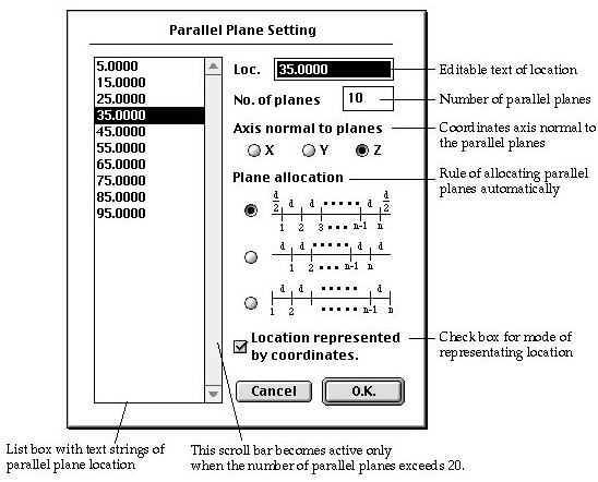
< Parallel plane setting dialog >
|
etting the number of parallel planes : Insert the number of parallel planes in the editable text box labeled as "No. of planes" |
|||||||||||||
|
Setting the orientation of the parallel planes :X Set the orientation of the parallel planes by turning one of the radio buttons labeled "X", "Y" and "Z" which represent direction normal to X, Y and Z coordinates axis, respectively. |
|||||||||||||
|
Deciding the rule of plane allocation : The parallel planes are initially located automatically at the points evenly dividing the total length of the model in the direction normal to the planes. There are 3 different rules of determining the division points. One of these 3 rules should be chosen by turning on the corresponding radio button. The example in the following table shows how the 10 parallel planes are located over the distance 100 by applying each one of the rules. |
|||||||||||||
|
<Rules of allocating the parallel plane>
|
|
Setting the mode of representing the location of a parallel plane : The location of a parallel plane may be represented either by coordinates or by ratio. If the mode is set to "by coordinates" the location of a parallel plane should be defined by the actual coordinates along the axis normal to the plane. Otherwise, location should be defined by the ratio scaled from 0 to 1 along the total length of the model in the direction normal to the plane. Check the box labeled "Location represented by coordinates" in order to set the mode to "By coordinates" or uncheck the box to set mode to "by ratio". |
||
|
Editing the text string of parallel plane locations: The locations of all the parallel planes are displayed as text strings in the list box of the dialog. The initial locations are determined automatically by the size of the selected parts, number of planes, etc. The parallel plane location may be altered by editing the text strings of the initial setting by the following steps: |
||
|
1) Click the text string to modify. |
||
|
The clicked text is highlighted, and an identical text string is placed in the editable text box in the dialog. |
||
|
2) Edit the text string in the editable text box. |
||
|
The selected text string in the list box is updated while the string in the editable text box is being edited. The edited string re p resents the modified location of the parallel plane. |
||
|
3) Repeat step 1) and 2) for all the parallel plane locations to modify. |
||
|
Edit the text strings one after another until all the relevant text strings are modified as desired. |
||
> Contouring on parallel planes
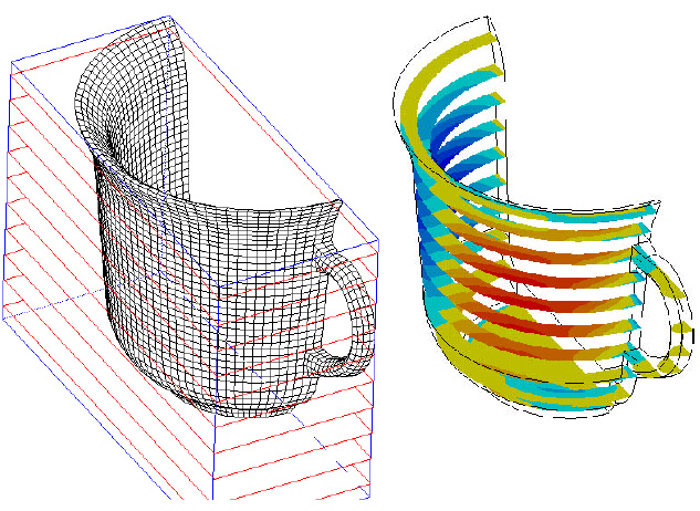
The parallel planes are used for contouring data inside 3-dimensional volumes. If parallel planes are set immediately prior to opening "Contour.." dialog, "Parallel Planes" item of the contouring object popup menu is enabled and is selected. If the selection of this popup menu item is not altered, the contour will be drawn on the parallel planes.
![]()
There are options setting the style of the surrounding boundary surface rendering. Refer to "Selecting the style of boundary surface rendering " for more detailed description on this subject.

< Setting the parallel plane and contouring on the plane >
|
|
|
|