![]()
| Postprocessing of Continuum Analysis > Visualizing Vector Data > Visualizing displacements by deformed shape and animation |
|
|
|
|
||
Visualizing displacements by deformed shape and animation
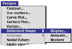 |
Displacements obtained from structural analysis are another typical example of vector data. As other vector data are re p resented by arrows, so can displacement data. However, we may get better insight on the displacements from the image of deformed shape than from arrows. All the displacement components are incorporated in one image of deformed shape. The nodal displacements are added, with a specified magnification factor, to the nodal coordinates to form new nodal coordinates which represent the exaggeratedly deformed model. Once the deformed shape is displayed, all the subsequent visualization of the model is done using the deformed nodal coordinates. However, a few operations including saving file, editing model data and solving, will automatically restore the undeformed original shape. This function is applicable only to structural analysis. |
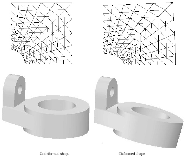
< Deformed shape of a planar structural model >
> Setting the display options
In oder to get a deformed shape, first select "Display..." item from
"Deformed Shape" submenu of ![]() menu.
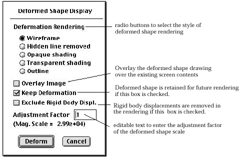
Then, "Deformed Shape Display" dialog appears on the screen as shown
in the following figure. There are a few items in this dialog, including the
type of rendering. Each item has a default setting or an initially suggested
value like deformation scale. Change the setting if necessary. Click
menu.
Then, "Deformed Shape Display" dialog appears on the screen as shown
in the following figure. There are a few items in this dialog, including the
type of rendering. Each item has a default setting or an initially suggested
value like deformation scale. Change the setting if necessary. Click ![]() button
if every item is set as desired. Then, the deformed shape will be rendered as
specified in the dialog. More details of setting the dialog is described in
the following.
button
if every item is set as desired. Then, the deformed shape will be rendered as
specified in the dialog. More details of setting the dialog is described in
the following.
< "Deformed Shape Display" dialog >
> Selecting the style of the deformed shape rendering
The deformed shape can be rendered in 4 different styles.
|
"Wireframe" : The deformed shape of the structural model is rendered in the form of wireframe without removal of hidden lines. |
|
|
"Hidden line removed" : The deformed shape of the structural model is rendered in the form of wireframe with removal of hidden lines. |
|
|
"Opaque shading" : The deformed shape of the structural model is rendered by opaque shading. |
|
|
"Transparent shading" : The deformed shape of the structural model is rendered by transparent shading. |
|
|
"Outline" : The deformed shape of the structural model is rendered by outline. |
> Overlaying the deformed shape image over the screen image
The deformed shape is drawn over the current image on the main window, if the "Overlay image" box is checked.
> Retaining the deformed shape in future rendering
The deformed shape may or may not be retained in the future rendering. If "Keep Deformation" box is checked, the deformed shape is used in the future rendering such as contouring. If you transform the view or change the rendering method, the rendering is updated with deformed shape. Otherwise, undeformed shape is used in the future rendering.
> Excluding the rigid body displacements from deformed shape
In case only a part of the model is to be visualized with its deformed shape, the displacements of other parts may sometimes dominate the overall picture. Thus the deformation of the interested part may be obscured by that of other parts. The portion of the displacements originated from other parts can be regarded as rigid body displacements for the displayed part, and therefore may be excluded fro m the deformation so that the image of the deformed shape is better scaled and positioned. Check the "Exclude rigid body displ." box in the dialog in order to remove the unwanted portion of the displacements.
> Setting the deformation scale
The displacements are usually very small as compared with the overall size of the structural model. Therefore, the displacements should be magnified to such a scale that their effects are discernible in the deformed shape. The deformation scale is the magnification factor that multiplies the displacements before adding them to the nodal coordinates. The deformation scale appropriate for display is initially determined by the software, and is shown in the dialog like "Mag.Scale=2.99e+04". The editable text item "Adjustment Factor" is provided for user's control of the displacement scale. The value is multiplied to the displacement scale and can be altered by editing the string in the editable test box. The altered value is applied in the subsequent display of the deformed shape.
> Visualizing the displacements by animation
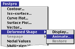 |
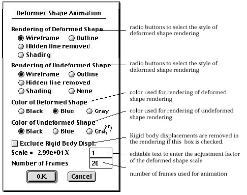
The displacements obtained from the analysis can be visualized by animation.
In oder to get a deformed shape, first select "Display..." item
from "Deformed Shape" submenu of |
The methods of rendering can be set independently for the deformed shape and the undeformed shape. The number of animation frame can be set using the editable text box in the dialog.
> Restoring undeformed shape
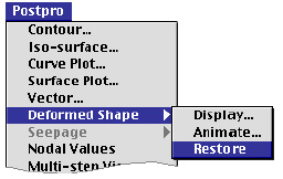
Once the deformed shape of a structural model is displayed, that shape is maintained
and used for subsequent data visualization like contouring, if "Keep Deformation"
option is used. In this case, the undeformed shape is restored by selecting
"Restore" item from "Deformed Shape" submenu of ![]() menu.
menu.
|
|
|
|