![]()
| Postprocessing of Continuum Analysis > Visualizing Scalar Data by Contours > Setting a cut plane for contouring |
|
|
|
|
||
Setting a cut plane for contouring
As described in the previous sections, the contours may be displayed on userdefined auxiliary planes such as a cut plane, cross planes, or parallel planes. These planes should be defined prior to contouring on them. "Cut plane", "Cross Planes" and "Parallel planes" items in the object type popup menu of "Contour Display" dialog become enabled only when the corresponding auxiliary planes are defined before opening the dialog.
A cut plane is a kind of volume visualization aid and can be used either as an auxiliary plane for contouring, or as a plane splitting the selected object(s). This section describes how to define a cut plane and how to use it as an auxiliary plane for contouring.
> Activating the cut plane setting mode
The cut plane setting mode should be activated in order to start defining a cut plane. This can be done by the following steps.
|
1) Start the volume selection tool by pressing |
|
|
The program is now ready to select volume object(s) in the model. |
|
|
2) Select object(s) in which the cut plane is to be defined. |
|
|
Select one or more object(s) which form a continuous volume which will contain the cut plane. |
|
|
3) Start the cut plane setting tool by pressing |
|
|
Get into the cut plane setting mode by clicking |
|
 |
The cut plane setting mode is deactivated simply by activating other tool in the tool palette.
> Setting a cut plane
The initial or the previous setting is shown, when the cut plane setting mode is activated. There are 2 different ways of setting the position and the orientation of a cut plane to the desired state
In order to reset the cut plane setting to the initial state, select "Reset
Plane" menu item from ![]() menu.
menu.
> Contouring on a cut plane
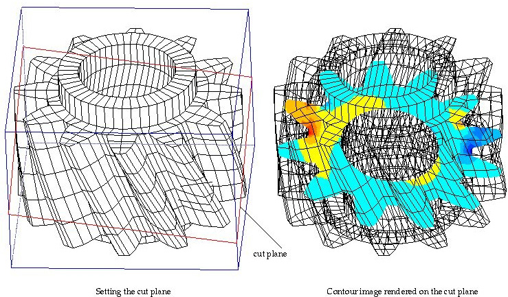
As explained above, the cut plane may be used for contouring. If a cut plane I set immediately prior to opening "Contour Display" dialog, "Cut Plane" item of the contouring object popup menu is enabled and is selected. (Refer to the previous section, "Setting contouring options".) If the selection of this popup menu item is not altered, the contour will be drawn on the cut plane.
![]()
There are options for setting the style of the surrounding boundary surface rendering. Refer to "Selecting the style of boundary surface rendering" for more detailed description on this subject.

< Setting the cut plane and contouring on the plane >
> Splitting objects using the cut plane
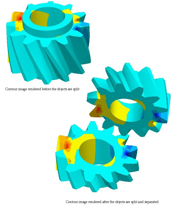
The cut plane may also be used as a plane splitting the selected objects. The split parts can be separated later for improved visualization of 3-dimensional volume data. Splitting and separating of volume objects can be achieved by the following steps:
If the objects are rendered in shading or contouring, rendering is updated while moving or rotating the selected part.

< Splitting and seperating objects using plane >
|
|
|
|